
How to Select BESS: Technical Fundamentals of Power vs. Energy
Usable vs. Nameplate Capacity
Never base your battery energy storage system sizing solely on nominal (nameplate) energy figures.
- Nameplate Capacity: The total theoretical energy stored in the battery cells under perfect factory conditions.
- Usable Capacity: The actual power you can extract to run your facility during daily operations.
- Operational Margins: Operating a system at 100% discharge accelerates battery degradation. We build in active software buffers and reserve margins so the system consistently delivers required discharge rates over a multi-year lifespan.
Power Rating (kW) vs. Stored Energy (kWh)
Proper hardware specification requires balancing instantaneous power output against total runtime duration.
- Power Rating (kW/MW): The maximum speed at which the system can deliver energy at any single moment.
- Stored Energy (kWh/MWh): The total total volume of energy contained within the system.
Example Configurations:
1 MW / 2 MWh System: Delivers 1 MW of power for 2 hours. Ideal for quick, high-impact demand charge management.
1 MW / 4 MWh System: Delivers 1 MW of power for 4 hours. Engineered for prolonged peak shaving and extended backup resilience.
Key Performance Metrics Checklist
Evaluating C-rate and depth of discharge parameters ensures your equipment matches operational demands without premature hardware aging.
| Metric | Recommended Range | Operational Significance |
|---|---|---|
| C-Rate | 0.25C to 1C | Defines charge and discharge speeds. A 0.5C rate delivers full capacity over 2 hours; a 1C rate delivers full capacity in 1 hour. |
| Depth of Discharge (DoD) | 90% – 95% | Balances active usable energy with long-term cell life. Restricting maximum discharge to 95% prevents deep-cycle stress. |
| Round-Trip Efficiency (RTE) | ≥ 88% – 94% | Measures total AC-to-AC conversion efficiency. Higher RTE minimizes energy lost during charging, standby, and inversion. |
How to Select BESS: Align Sizing with Operational Use Cases
Choosing the right battery energy storage system starts with defining the exact operational job the equipment must perform. Matching storage capacity directly to facility load profiles avoids overpaying for unnecessary capacity while guaranteeing operational reliability.
Core Application Breakdown
- Demand Charge Management & Peak Shaving: We calculate peak load spikes using 12-month utility interval data to isolate expensive demand surges. Deploying targeted peak shaving and load shifting solutions cuts utility surcharges by 30% to 35%.
- Solar + Storage Self-Consumption: We match onsite PV generation profiles directly with battery storage to capture excess solar power produced during low-demand hours. This strategy pushes solar self-consumption rates beyond 90%.
- Critical Backup & Microgrid Resilience: For sensitive industrial manufacturing lines, fast transfer speeds are mandatory. Integrating specialized microgrid energy storage delivers sub-10ms switchover times, protecting facility equipment from voltage sags and unplanned grid outages.
- EV Charging Infrastructure Buffering: High-power DC fast chargers create sudden, severe utility demand spikes. Using a BESS as an energy buffer absorbs these surges, cutting costly transformer upgrade expenditures by up to 50%.
Select Battery Chemistry and Form Factor

Choosing the right battery chemistry and enclosure design determines system safety, thermal performance, and long-term expansion costs.
Cell Chemistry: LFP vs. NMC
For modern projects, Lithium Iron Phosphate (LiFePO4 / LFP) is our top recommendation over Nickel Manganese Cobalt (NMC). LFP delivers superior thermal stability, predictable non-gaseous degradation, and a longer operational lifespan.
| Performance Metric | Lithium Iron Phosphate (LiFePO4) | NMC & Alternative Chemistries |
|---|---|---|
| Cycle Life | >= 6,000 cycles | 2,500 – 4,000 cycles |
| Thermal Safety | High thermal runaway threshold | Lower thermal stability threshold |
| Degradation Profile | Non-gaseous, linear capacity loss | Higher sensitivity to thermal stress |
| Replacement Overhead | Low total cost of ownership | Frequent cell augmentation needed |
Form Factor Engineering: Cabinets vs. Containers
Physical footprint depends directly on site limits and required energy density:
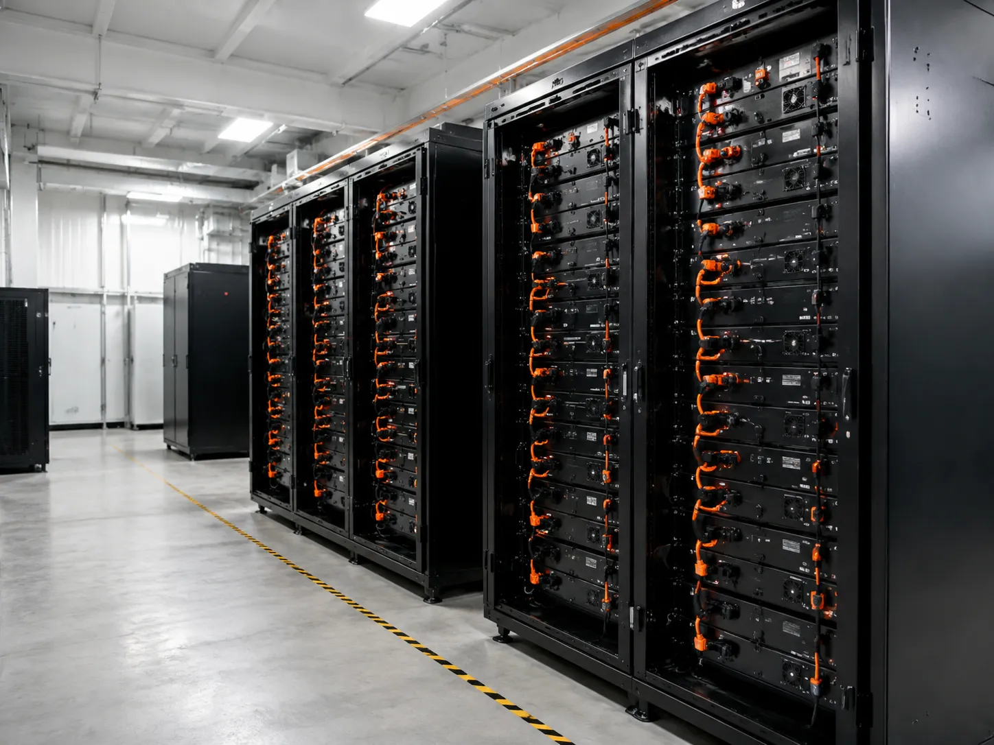
- Modular Energy Storage Cabinets: Compact units designed for indoor or localized outdoor footprints in flexible commercial and industrial energy storage systems.
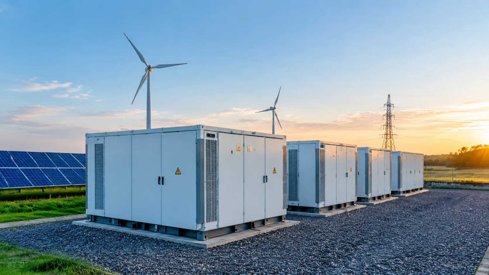
- Containerized BESS Units: High-density, factory-assembled setups built for large facilities and utility installations. Deploying standardized containerized energy storage systems offers up to 5MWh per unit, cutting down civil engineering work and field integration time.
Future System Expansion and Augmentation
Power demands rarely remain static. We design system topologies with oversized DC busbars and pre-wired parallel rack connections from day one. This modular setup lets you add battery capacity in parallel as your load grows, avoiding costly inverter replacements or complete system redesigns.
Step 3: Evaluate Safety Architecture & Thermal Management
Active Liquid Cooling vs. Forced Air Cooling
While forced air cooling has a lower initial cost, BESS thermal management liquid cooling provides superior performance and protection for high-utilization commercial assets.
- Thermal Uniformity: Active liquid cooling maintains core cell temperature variance within a tight $\le$2°C delta across the entire enclosure, eliminating hot spots.
- Lifespan Extension: Uniform cooling slows electrochemical degradation, extending overall battery cycle life by up to 20%.
- Volumetric Efficiency: Liquid coolant plates eliminate bulky air ducting, enabling much higher energy density within a smaller physical footprint.
Multi-Tier BMS Protection
A reliable battery management system 3-tier architecture acts as the primary digital defense mechanism, actively preventing overcharging, overdischarging, and cell imbalance. We deploy advanced BMS and EMS integration solutions to deliver full operational visibility across every single battery module.
| BMS Level | Primary Function | Monitored Parameters |
|---|---|---|
| Module Level | Local cell monitoring & active balancing | Individual cell voltage, localized temperature |
| Rack Level | String isolation & current control | Rack SOC, SOH, string current, insulation resistance |
| System Level | Site integration & emergency shutoff | System-wide telemetry, PCS communication, fault routing |
Integrated bidirectional active cell balancing continuously transfers charge from high-energy cells to lower-energy cells during duty cycles, eliminating capacity drift and ensuring maximum usable energy over time.
Fire Safety & Deflagration Protection
A comprehensive fire safety strategy relies on multi-layered detection and rapid suppression to mitigate thermal runaway propagation:
- Early Off-Gas Detection Sensors: Detect minute chemical off-gassing (such as hydrogen and VOCs) minutes before thermal runaway or smoke generation begins.
- Pack-Level Targeted Aerosol Suppression: Module-isolated fire suppression deploys localized aerosol directly inside the affected pack to snuff out thermal events instantly.
- Compliance & Certification: Ensure full alignment with NFPA 855 guidelines and rigorous UL 9540A thermal runaway propagation testing to satisfy local utility and fire authority requirements.
How to Select BESS: Verify Protocol Interoperability & Software Control
Industrial Hardware Communication
Your battery energy storage system must talk directly to your site’s hardware without proprietary lock-in or complex protocol converters. We build and select systems with native support for standard industrial protocols:
- Modbus TCP & CAN Bus: Delivers high-speed, low-latency telemetry across individual battery modules, racks, and system controllers.
- Open REST APIs: Enables secure cloud connectivity, automated data logging, and seamless third-party software integration.
The Software Management Stack
A fully optimized BESS relies on two critical software components working in harmony:
| Component | Primary Function | Key Features to Look For |
|---|---|---|
| Power Conversion System (PCS) | Power Conditioning & Inversion | • High power conversion system (PCS) bidirectional inverter efficiency • Real-time power factor correction • Sub-second response times for grid stability |
| Energy Management System (EMS) | Strategy & Dispatch Optimization | • Energy management system EMS software with cloud-edge telemetry • AI-driven dispatch algorithms for automated Time-of-Use (TOU) arbitrage • Predictive peak shaving based on historical load profiles |
Facility System Interoperability
Your energy storage shouldn't operate in a silo. True efficiency comes from unifying your storage with existing site controls. Through our specialized custom ESS integration, we ensure complete interoperability with facility SCADA and Building Management Systems (BMS), giving you centralized visibility and control over your entire enterprise energy footprint.
How to Select BESS: Certifications and Turnkey Vendor Capabilities

Non-Negotiable Safety Certifications
Deploying commercial and industrial energy storage requires strict compliance with international safety standards to mitigate thermal, electrical, and structural risks. Never compromise on verified certifications.
- UL 9540A: Evaluates thermal runaway fire propagation behavior at the cell, module, and unit level.
- UL 1973 & IEC 62619: Ensures battery cell and pack safety under electrical, mechanical, and thermal stress.
- CE & UN 38.3: Validates structural safety, electromagnetic compatibility, and safe transport standards.
- ISO 9001: Guarantees strict manufacturing quality management across all production lines.
Verifying full compliance through validated quality certifications early in your BESS procurement checklist prevents costly permitting delays and ensures local fire code approval.
The 6-Phase Turnkey Execution Model
A successful storage deployment requires end-to-end management rather than piecemeal vendor sourcing. We execute projects using a comprehensive, 6-phase turnkey project delivery model:
- Site Load Profile Analysis: Analyzing 12-month utility interval data to establish exact peak demand thresholds.
- Custom System Engineering: Matching cabinet or containerized footprints to site layout and electrical limits.
- Factory Acceptance Testing (FAT): Pre-commissioning hardware, PCS, and software integration before shipment.
- Civil & Electrical Installation: Foundation pad engineering, high-voltage conduit placement, and transformer wiring.
- Commissioning & Grid Interconnection: Completing utility interconnection agreements, protection settings, and live synchronization.
- 24/7 Operations & Maintenance (O&M): Continuous cloud-edge telemetry monitoring to protect system health.
Financial Payback & Total Cost of Ownership (TCO)
Evaluating BESS Total Cost of Ownership (TCO) and ROI requires balancing initial capital expenditure (CapEx) against operational savings (OpEx).
| Financial Factor | System Impact & Payback Target |
|---|---|
| Tax Incentives & Subsidies | Leveraging the Investment Tax Credit (ITC) and local grants can offset initial CapEx by 30% to 50%. |
| OpEx Reduction | Liquid cooling and active balancing reduce annual capacity degradation, preserving system value. |
| Payback Timeline | Combining demand charge management with time-of-use arbitrage yields a 3-to-5-year payback window. |
Strategic Partnering with Percenec Energy
At Percenec Energy, we eliminate long-term operational risk through complete vertical integration. By manufacturing our own hardware and developing proprietary BMS and EMS software under one roof, we deliver seamless compatibility and maintain a 99.9% system uptime track record for mission-critical facilities globally.
Frequently Asked Questions
What is the difference between usable energy capacity and rated nameplate capacity in a BESS?
Nameplate capacity is the total theoretical energy a battery system can hold when brand new. Usable capacity is the actual amount of energy available for daily operational use. The difference comes down to three operational factors:
- Depth of Discharge (DoD) Limits: Keeping a 5–10% reserve buffer to protect cells from deep discharge damage.
- Conversion Efficiency: AC-to-DC and DC-to-AC losses across the inverter and transformer.
- Lifecycle Degradation: Expected capacity retention over 10 to 15 years of continuous cycling.
When calculating battery energy storage system sizing, we always spec systems around usable kWh at year 10 rather than initial nominal capacity to prevent asset underperformance.
How does liquid cooling compare to air cooling in terms of system lifespan and ROI?
Liquid cooling maintains exact thermal uniformity across battery packs, making it the benchmark for high-duty deployments.
| Performance Metric | Liquid Cooling | Forced Air Cooling |
|---|---|---|
| Cell Temperature Uniformity | Excellent (<= 2°C delta) | Moderate (>= 5°C delta) |
| Battery Cycle Life Impact | Extends lifespan by up to 20% | Standard baseline degradation |
| Cabinet Footprint | Compact, high energy density | Requires larger airflow spacing |
| Lifetime ROI & TCO | Lower TCO / Higher lifetime return | Lower initial CapEx / Higher degradation |
For heavy daily cycling in commercial and industrial energy storage, BESS thermal management liquid cooling protects core cells and maximizes financial returns.
What is the average ROI payback period for a Commercial & Industrial BESS project?
Most commercial and industrial energy storage projects achieve full payback within 3 to 5 years. Key drivers boosting project ROI include:
- Demand Charge Reduction: Shaving peak monthly kW surges by 30% to 35%.
- Time-of-Use Arbitrage: Storing cheap off-peak power and discharging during peak tariff windows.
- Incentives & Tax Credits: Utilizing federal tax incentives (ITC) and local energy rebates.
Review our complete BESS buying guide to see how to calculate step-by-step payback models for your specific utility tariff structure.
Can a modular BESS system be expanded after initial installation?
Yes. Modern modular BESS engineering utilizes flexible DC busbar topologies and expandable control software. You can install an initial baseline capacity (e.g., 250 kW / 500 kWh) and integrate additional modular energy storage cabinets or high-density containerized units in parallel as facility loads, EV fast-charging demand, or solar PV capacity grow.
Which fire safety standards are mandatory for C&I battery energy storage systems?
Commercial battery energy storage systems must meet rigorous fire safety standards to secure local permitting and insurance approval:
- UL 9540 & UL 9540A: Mandatory system-level safety listing and thermal runaway propagation testing.
- UL 1973: Core safety standard for energy storage battery cell and module packs.
- NFPA 855: Standard for the installation of stationary energy storage systems.
- IEC 62619 & UN 38.3: International safety standards for industrial lithium batteries and transport security.
Explore our dedicated BESS frequently asked questions page for additional guidance on compliance, system design, and grid interconnection steps.
Related Sources
- https://energylibrary.tesla.com/docs/Public/EnergyStorage/Powerwall/General/Compliance
- https://heavendesigns.in/blog/bess-sizing-ci-solar-engineering/
- https://www.bsl-battery.com/
- https://www.nfpa.org/codes-and-standards/nfpa-855-standard-development/855
- https://sparklab.engr.uky.edu/sites/spark/files/2022%20IEEE%20IAS%20UK%20SPARK%20Generalized%20Energy%20Storage%20CTA%202045%20DER.pdf