Are high upfront capital costs and inflexible equipment holding back your facility or power plant expansion? The primary risk for project developers, facility managers, and EPC contractors is investing in locked-in energy storage capacity that becomes obsolete or oversized before reaching full payback. A true scalable battery energy storage system solves this bottleneck by allowing you to deploy what you need today and expand capacity dynamically as demand grows.
Modular BESS Architecture: C&I Cabinets to Containerized Utility Blocks
We engineer our modular hardware to support seamless linear growth across diverse commercial and utility application footprints.
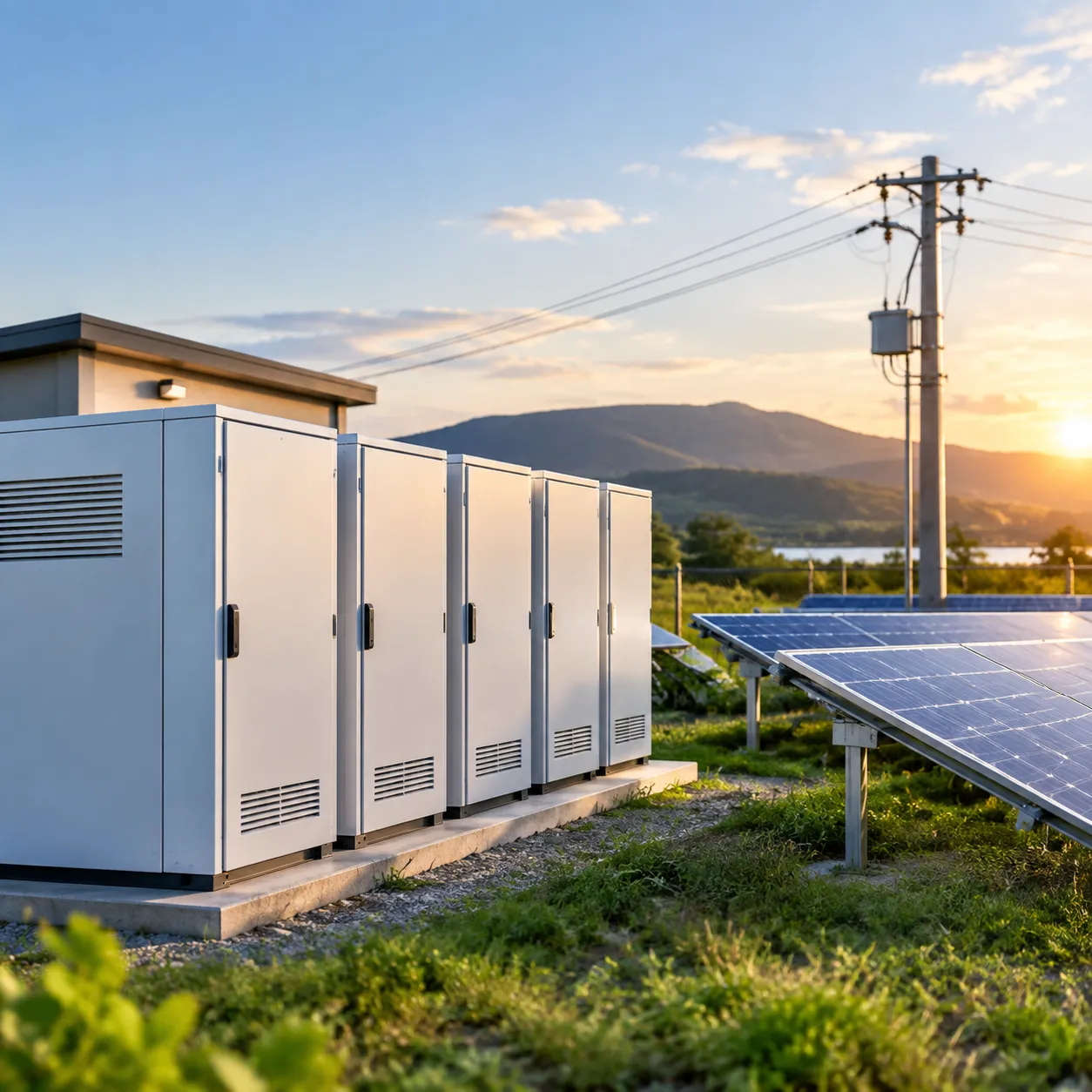
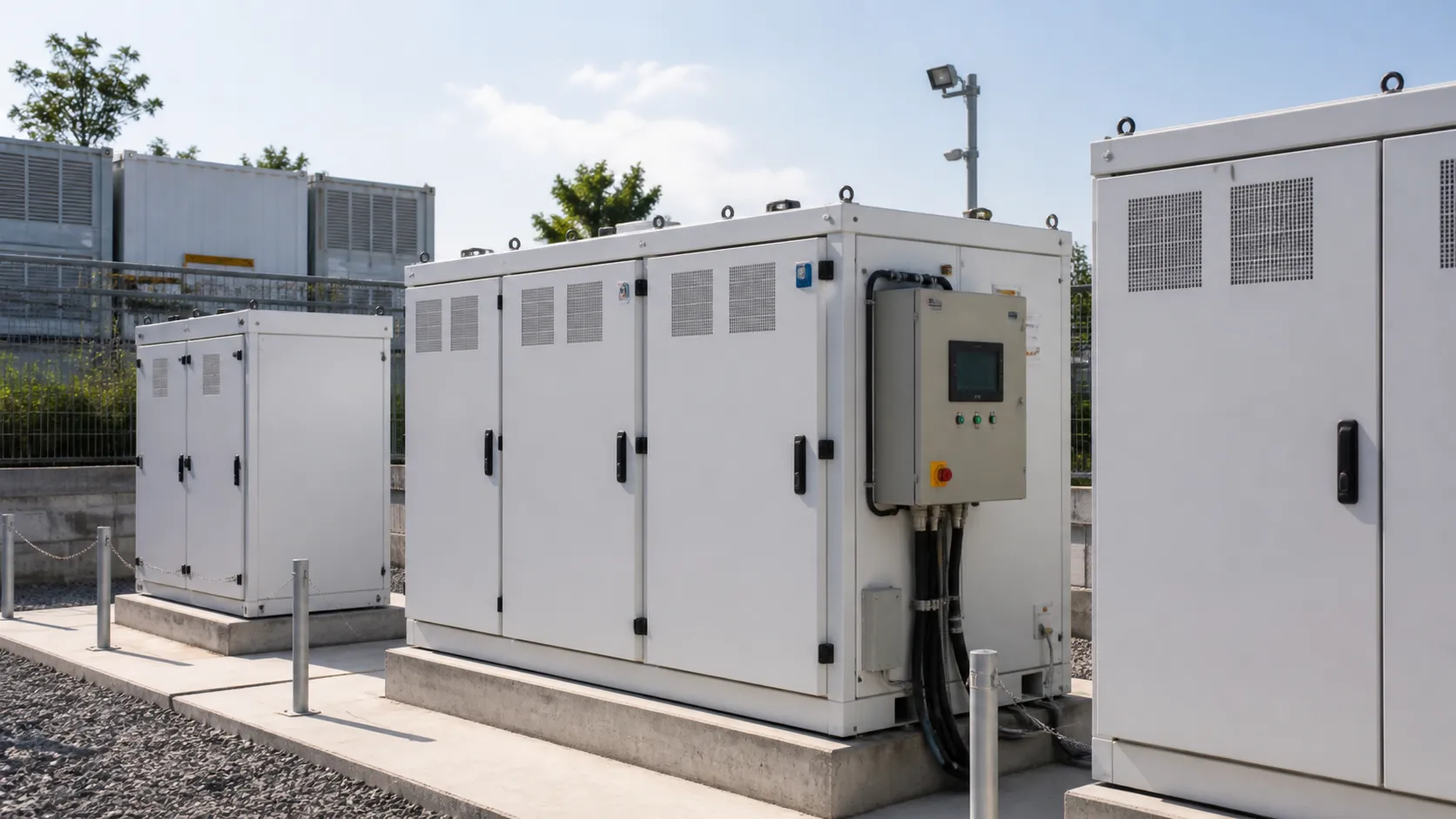
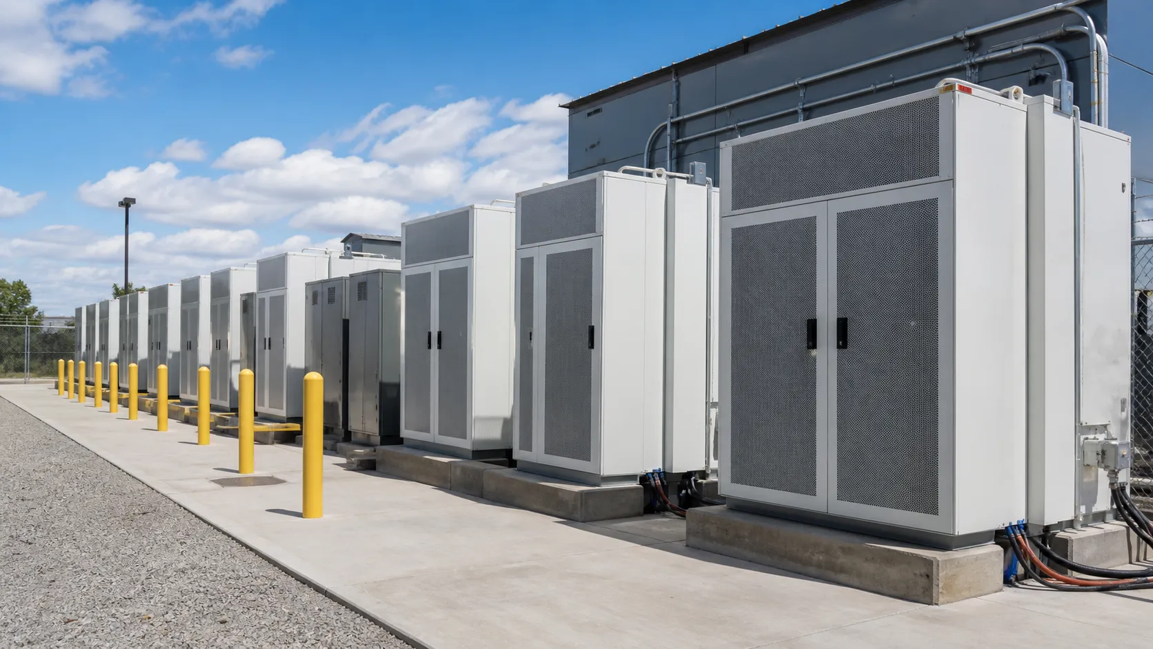
- C&I Outdoor Cabinets: Distributed, high-density enclosures ranging from 100–500 kWh, ideal for commercial facilities targeting space-constrained demand charge management.
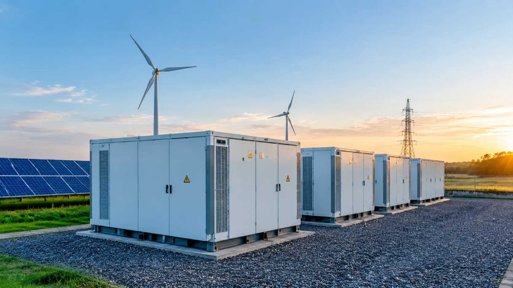
- 5MWh Utility Storage Blocks: Fully integrated 20 ft ISO high-cube containerized battery storage systems designed for utility-scale grid stabilization, IPP assets, and large renewable integration.
Parallel Modular Expansion Without BOP Infrastructure Overhauls
Scaling energy capacity should never require redesigning your entire power infrastructure.
- Dynamic Cabinet Expansion: Add battery modules or additional cabinets in parallel whenever your load profile expands.
- Zero BOP Disruption: Scale battery energy capacity without replacing existing balance of plant (BOP) hardware, switchgear, or main transformer capacity.
- Reduced Initial CAPEX: Align capital expenditure with actual energy demand phases, significantly optimizing your project’s lifetime economics.
Engineering High-Density Safety, Lifespan, and Thermal Control
We combine tier-1 cell chemistry with advanced thermal management to maximize asset uptime and protect capital investment.
| Feature | Technical Specification | Operational Advantage |
|---|---|---|
| Cell Chemistry | High-safety LiFePO4 (LFP) | Delivers >= 6,000 cycles at 80% Depth of Discharge (DoD) |
| Thermal Management | Advanced liquid cooling architecture | Maintains cell-to-cell delta <= 2.5°C during continuous high-rate cycling |
| System Cooling Efficiency | Closed-loop liquid vs. air cooling | Reduces parasitic auxiliary power consumption up to 40% |
Multi-Tier Fire Safety and International Compliance
Safety is embedded directly into hardware design at the module, rack, and enclosure level:
- Pack-Level Off-Gas Detection: Detects early thermal runaway indicators minutes before thermal spikes occur.
- Integrated Suppression: Direct pack-level aerosol and gas fire suppression limits damage to individual modules.
- Certified Bankability: Fully compliant with UL 9540A, UL 1973, and IEC 62619 safety standards to streamline local AHJ approvals and project financing.
Software Control Layer: Optimizing Scalable Battery Energy Storage System Performance

3-Tier BMS Architecture with Active Balancing
Battery degradation starts at the cell level. We eliminate performance bottlenecks using a 3-tier battery management system (BMS) that delivers continuous, sub-second diagnostics across three distinct operational layers:
- Level 1 (Cell Level): Direct monitoring of cell voltage, temperature, and impedance. Active bidirectional cell balancing continuously shifts energy from higher-charged cells to lower-charged ones, keeping capacity variance below 1% and extending overall pack life.
- Level 2 (Rack Level): Controls string-level circuit breakers, calculates precise State of Charge (SoC) and State of Health (SoH), and manages localized cooling controls.
- Level 3 (System Level): Aggregates multi-rack data, executes safety shutdowns, and interfaces directly with site-level controllers.
Deploying a high-performance commercial energy storage system with BMS allows facility operators to avoid thermal risks while maintaining peak round-trip efficiency (RTE) over years of heavy usage.
Cloud-Edge EMS & Dynamic AI Dispatch
Our energy management system (EMS) software combines local edge computing with cloud analytics to turn stored energy into automated operational savings.
| Feature | Edge Capabilities | Cloud Analytics Capabilities |
|---|---|---|
| Response Speed | Millisecond local execution (< 10 ms) | Historical trend modeling & optimization |
| Primary Function | Autonomous load management & microgrid islanding | Machine learning for load & solar prediction |
| Operational Duty | Direct inverter & protection relay control | Dynamic spot-market bidding & tariff optimization |
The cloud engine analyzes historical usage patterns, real-time weather forecasts, and dynamic time-of-use (TOU) rate structures to deliver maximum peak demand charge reduction. Meanwhile, the local edge controller runs autonomously to maintain site stability even if cloud connection drops.
Open Protocol Interoperability (Modbus, CAN, Open APIs)
Proprietary software lock-in restricts long-term site expansion. We build our control software on universally recognized communication standards, allowing painless integration with existing plant SCADA and Building Management Systems (BMS):
- Industrial Fieldbus Protocols: Native support for Modbus TCP/RTU, CAN bus, and DNP3.
- APIs & Cloud Protocols: Open RESTful APIs for integration with third-party Virtual Power Plant (VPP) aggregators and utility dispatch platforms.
- Multi-Vendor Integration: Smooth handshakes with major power conversion systems (PCS), microgrid controllers, and EV fast-charging networks without custom middleware.
High-Value Commercial & Utility Applications
Industrial Peak Shaving
Spike demand during heavy equipment startup leads to massive utility demand surcharges. Our automated dispatch algorithms discharge power during peak operational windows, delivering up to a 35% average reduction in peak demand surcharges. By deploying targeted peak shaving and load shifting solutions, industrial facilities slash annual power bills without altering production schedules.
Commercial Energy Arbitrage & Solar Integration
We monetize time-of-use (TOU) rate differentials by storing cheap grid energy during off-peak hours and discharging when power pricing peaks. For sites with solar, our systems dynamically route excess generation back into the battery, driving onsite PV self-consumption past 90% while insulating facilities from volatile utility rate hikes.
High-Power EV Charging Buffering
Fleet electrification often requires massive grid feed upgrades that delay projects by years. By deploying localized storage buffers that supply instantaneous high-kw bursts during vehicle charging, facilities eliminate severe demand spikes while reducing grid infrastructure upgrade costs by up to 50%.
Mission-Critical Backup & Microgrids
| Application Parameter | Performance Metric | Operational Impact |
|---|---|---|
| Switchover Time | < 10 ms seamless transfer | Zero operational disruption during grid outages |
| Control Architecture | Autonomous islanding microgrid controller | Full site power autonomy during extended blackouts |
| System Availability | 99.9% uptime track record | Continuous protection for mission-critical loads |
By deploying specialized microgrid energy storage solutions, mission-critical industrial sites and commercial hubs maintain seamless operation without relying strictly on dirty, expensive diesel generators.
Financial Modeling & Turnkey Execution
Fast-Tracking Payback in 3–5 Years
Deploying a scalable battery energy storage system requires a clear, data-driven financial pathway. We model multi-stream revenue strategies—combining peak demand surcharge reduction, time-of-use (TOU) arbitrage, and grid participation—to ensure capital recovery within a typical 3–5 year window. By matching battery dispatch profiles to specific utility tariffs and local incentive programs, we maximize overall project bankability from day one.
Minimizing LCOS Through Staged Capacity Expansion
Over-provisioning energy storage upfront ties up critical capital and leads to unnecessary cell degradation before capacity is fully utilized. A staged expansion strategy significantly lowers the Levelized Cost of Storage (LCOS) by deferring upfront CAPEX. Facility operators can begin with compact energy storage cabinets and scale into multi-megawatt blocks only as load demands increase, ensuring high balance-of-plant (BOP) utilization across the asset's operational life.
Percenec Energy’s 6-Phase Delivery Model
- Site Assessment: Rigorous engineering evaluation of electrical infrastructure, site safety buffers, and utility connection points.
- ROI Modeling: High-resolution software simulations mapping real-time facility load profiles against local utility rate structures.
- Manufacturing: Quality-controlled production and factory acceptance testing of our integrated battery energy storage systems.
- Grid Connection: Direct coordination with regional utility authorities to manage interconnection protocols and regulatory compliance.
- Commissioning: Comprehensive on-site validation of thermal controls, cloud EMS dispatch response, and multi-tier fire safety systems.
- 24/7 Lifetime O&M: Continuous remote telemetry monitoring, predictive maintenance alerts, and guaranteed SLA performance for the entire operating life.
Vendor Evaluation Checklist for a Scalable Battery Energy Storage System
Selecting the right partner for a scalable battery energy storage system requires looking beyond baseline battery pricing. To safeguard capital investment and guarantee long-term bankability, we evaluate suppliers against four non-negotiable performance criteria:
- Expansion Flexibility: Verify that the system supports plug-and-play modular addition without forcing expensive balance-of-plant (BOP) overhauls, transformer swaps, or extended facility downtime.
- Software Openness: Require open communication protocols (Modbus TCP, CAN, and open REST APIs) to avoid vendor lock-in and guarantee smooth integration with facility SCADA, microgrid controllers, or building management software.
- Proven Field Reliability: Inspect field performance records to confirm a consistent 99.9% uptime track record across active C&I or utility installations, ensuring uninterrupted peak demand charge reduction and backup availability.
- Single-Source Execution: Work with a vendor that takes full accountability from design to disposal. Our end-to-end project delivery model covers initial feasibility, manufacturing, grid connection, commissioning, and continuous 24/7 O&M under a single service-level agreement.
Before issuing an RFP or locking in system specifications, review our complete BESS buying guide to streamline your hardware and software selection process.
Frequently Asked Questions (FAQs) About Scalable BESS
What makes a BESS architecture truly scalable?
A truly scalable battery energy storage system relies on modular hardware and dynamic software designed for linear capacity expansion. Instead of replacing balance-of-plant (BOP) components or overhauling transformers, true scalability allows you to add battery modules or cabinets dynamically.
- Hardware Modularity: Seamlessly scales from 100–500 kWh C&I cabinets up to 5 MWh containerized utility blocks.
- Software Auto-Configuration: A multi-tier BMS instantly recognizes newly integrated racks, automatically balancing dynamic loads without system downtime.
How does modular battery expansion reduce LCOS and upfront CAPEX?
Staged capacity expansion prevents heavy upfront capital expenditure (CAPEX) on unutilized battery capacity. By right-sizing your initial footprint and expanding modules as your load demands or energy arbitrage revenues grow, you optimize your cash flow and significantly lower your Levelized Cost of Storage (LCOS).
To explore hardware configurations built to scale on demand, view our turnkey energy storage products.
Which safety standards apply to scalable BESS installations?
Local authorities, insurers, and grid operators require strict compliance to guarantee operational security:
- UL 9540A: Evaluates thermal runaway fire propagation performance at the cell, module, and unit levels.
- NFPA 855: Defines standards for installation, hazard mitigation, system sizing, and spatial separation.
- UL 1973 & IEC 62619: Mandate strict electrical, mechanical, and functional safety for energy storage battery packs.
Our deployments strictly comply with these global regulations, backed by full quality certifications to ensure rapid permitting, seamless grid connection, and bankable execution.