What Is Energy Storage System Architecture?
Defining Energy Storage System Architecture
At its core, energy storage system architecture refers to how individual components—such as battery modules, power conversion units, control software, and safety systems—are interconnected and coordinated. It establishes the physical and logical blueprint that governs how power and data flow across the entire facility.
A common pitfall in project planning is confusing architecture with system sizing. While both are critical to effective energy storage system design, they address fundamentally distinct technical challenges:
| Architectural Aspect | System Architecture | System Sizing |
|---|---|---|
| Primary Focus | System topology, component integration, and control hierarchy | Capacity determination and power rating |
| Key Metrics | Bus configuration (AC vs. DC), coupling points, communication protocols | Total energy ($kWh$), continuous/peak power ($kW$), run time |
| Engineering Impact | Determines safety, scalability, redundancy, and conversion efficiency | Ensures the system meets site load demands and duty cycles |
Why Architecture Directly Drives System Performance
The chosen battery energy storage system architecture acts as the primary driver of operational performance and project return on investment (ROI). A flawed design creates bottlenecks that no amount of battery capacity can fix.
- Round-Trip Efficiency: Minimizes energy conversion steps across transformers and inverters to cut parasitic losses.
- System Reliability: Integrates redundant communication paths and fault isolation to keep critical loads online during single-component failures.
- Operational Safety: Controls short-circuit currents and prevents thermal runaway propagation through structural isolation.
- Scalability: Enables seamless parallel expansion without requiring a complete overhaul of existing power conversion infrastructure.
- Simplified Maintenance: Isolates specific racks or strings for service without forcing complete system shutdowns.
- Maximum ROI: Lower balance-of-system (BOS) costs and extended asset lifespan significantly improve financial paybacks.
Core Goals of a Well-Designed ESS
In our engineering practice, every energy storage system design must satisfy five fundamental performance targets:
- Stable Power Delivery: Maintains clean voltage and frequency support across variable load profiles.
- Sub-Second Response Time: Executes rapid power dispatch for grid stabilization, peak shaving, and seamless microgrid transition.
- High-Efficiency Conversion: Optimizes round-trip efficiency (RTE) across battery cells, PCS, and thermal management units.
- Fail-Safe Operation: Guarantees comprehensive safety under extreme environmental conditions and electrical fault scenarios.
- Future-Proof Integration: Standardizes interfaces to allow straightforward capacity additions and third-party software integration.
Main Components of an Energy Storage System
Battery Pack and Rack Architecture
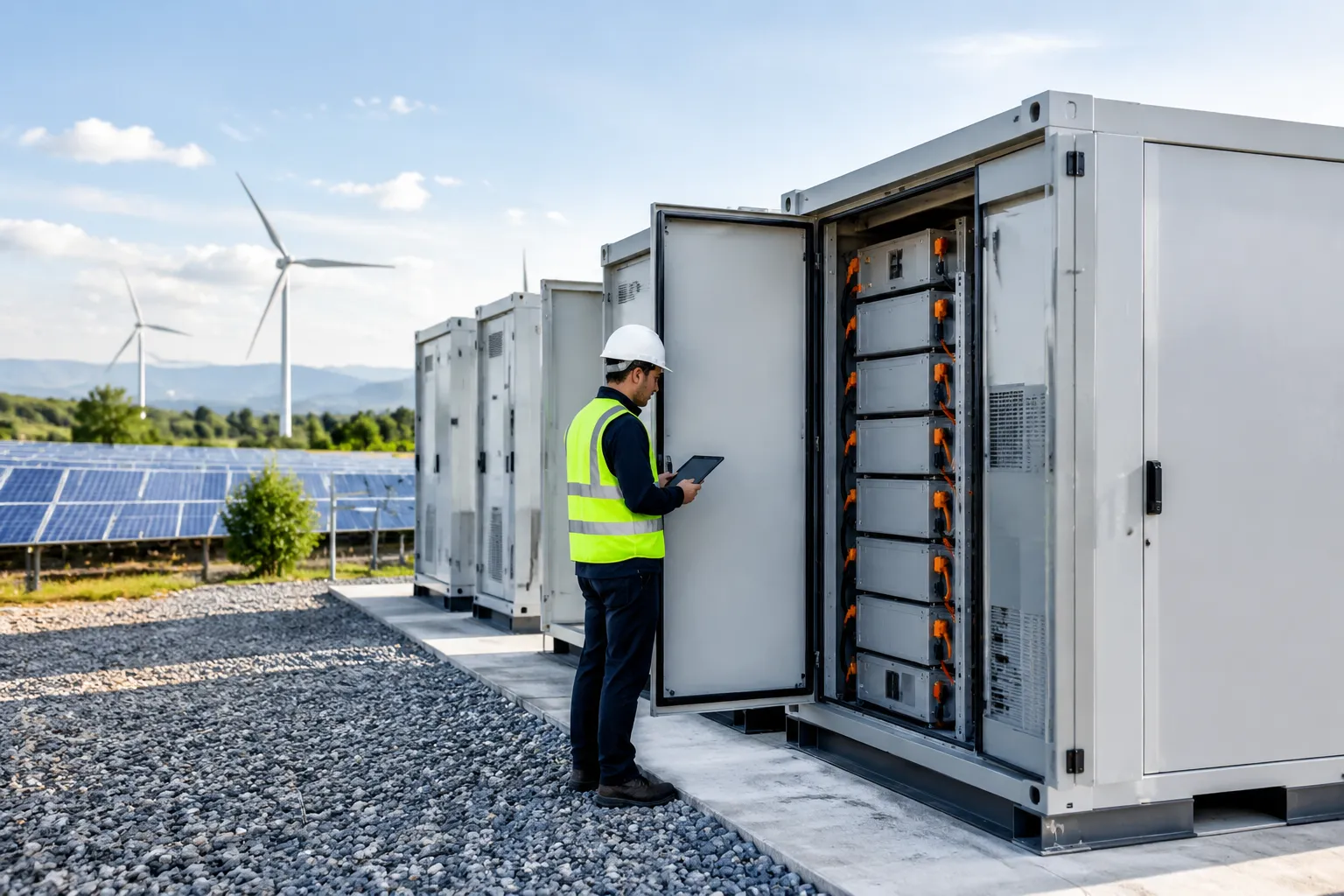
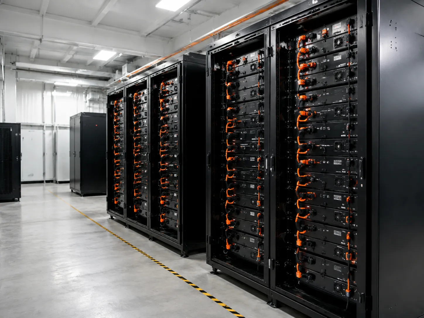
We rely primarily on Lithium Iron Phosphate (LiFePO4) chemistry due to its superior thermal stability, extended cycle life, and inherent safety profile. Our commercial lithium battery energy storage system with BMS utilizes modular rack and standardized container formats, allowing flexible layout designs and fast field installation.
Battery Management System (BMS) Architecture
Our battery management system architecture operates down to the individual cell level, continuously tracking voltage, current, cell temperature, and state of charge (SOC). The BMS executes multi-tier protection logic and rapid fault handling to isolate hardware anomalies before they escalate.
Power Conversion System Design
A high-performance power conversion system design manages bidirectional AC/DC conversion with minimal losses. The PCS controls active and reactive power flow, manages charge and discharge sequences, and provides fast grid regulation to ensure continuous power quality.
Energy Management System Software
The energy management system software acts as the top-level intelligent operator. It runs real-time dispatch strategies, automated peak shaving, energy arbitrage, load control, and backup power logic. For utility operations, our scalable battery energy storage system for utilities uses advanced EMS algorithms to optimize dispatch schedules and maximize ROI.
Inverter, Transformer, and Switchgear
These heavy electrical components link the DC storage core to the AC grid or industrial load:
Inverters: Convert DC power from the batteries into clean, synchronized AC power.
Transformers: Step up or step down voltage levels to match local utility interconnections.
Switchgear: Provide protection coordination, circuit interruption, and safe electrical isolation during maintenance.
ESS Thermal Management
Effective ESS thermal management maintains strict temperature consistency across all battery cells to prevent uneven degradation. We deploy liquid cooling for high-density, high-C-rate applications and air cooling for lower-density installations, optimizing heat dissipation and auxiliary power usage.
Fire Protection and Safety Devices
Safety is embedded directly into our energy storage system architecture. Systems feature multi-stage off-gas detection, pack-level automated fire suppression, emergency shutdown (ESD) circuits, and physical containment barriers compliant with international energy storage safety standards.
Communication and Monitoring Layer
Our control topology uses robust communication protocols—including Modbus TCP, CAN bus, and RESTful APIs—to connect hardware with SCADA systems. This setup enables continuous remote monitoring, detailed data logging, and instant fault notifications across the entire asset network.
How Energy Storage System Architecture Works
An optimized energy storage system architecture relies on two synchronized pathways: the physical power flow path that transfers electricity and the digital control flow path that directs operations.
Power Flow Path
The power flow path governs how energy moves through the system during charge and discharge cycles:
- Energy Ingestion: Power originates from the utility grid or onsite generation such as solar PV arrays.
- AC/DC Conversion: The bidirectional Power Conversion System (PCS) converts incoming AC electricity into DC power to charge the battery modules.
- Energy Storage: Electrical energy is stored chemically inside high-density battery cell racks.
- Discharge and Load Support: When site demand peaks, DC power flows from the batteries back into the PCS, converting to AC power to feed facility loads or export directly to the grid.
Control Flow Path
The control flow path manages decision-making, monitoring, and execution across the entire energy storage system design:
- Cell-Level Safety (BMS): The battery management system architecture constantly measures individual cell voltages, currents, and temperatures to maintain precise operational limits.
- System Dispatch (EMS): The energy management system software analyzes electricity tariffs, peak load demand, and dispatch logic to calculate optimal charge and discharge schedules.
- Command Execution (PCS): The power conversion system design receives real-time setpoints from the EMS and converts power with sub-second response times.
- Fault Response Sequence: If operational limits are breached, safety logic triggers immediate alarms, opens isolation switches, and brings the system to a safe state.
Why Coordination Between BMS, PCS, and EMS Matters
Seamless ESS component integration between the BMS, PCS, and EMS is essential to avoid control conflicts and maintain high round-trip efficiency. For example, if the EMS commands a rapid discharge cycle while the BMS detects elevated cell temperatures, unified control ensures safety protocols override command signals without dropping system availability.
By synchronizing these three core layers, we prevent control lag, eliminate unexpected shutoffs, and extend battery cycle life. For complex site requirements, our specialized BMS and EMS integration ensures seamless communication across all hardware components, protecting your investment while maintaining fast, predictable power delivery.
Key Types of Energy Storage System Architectures
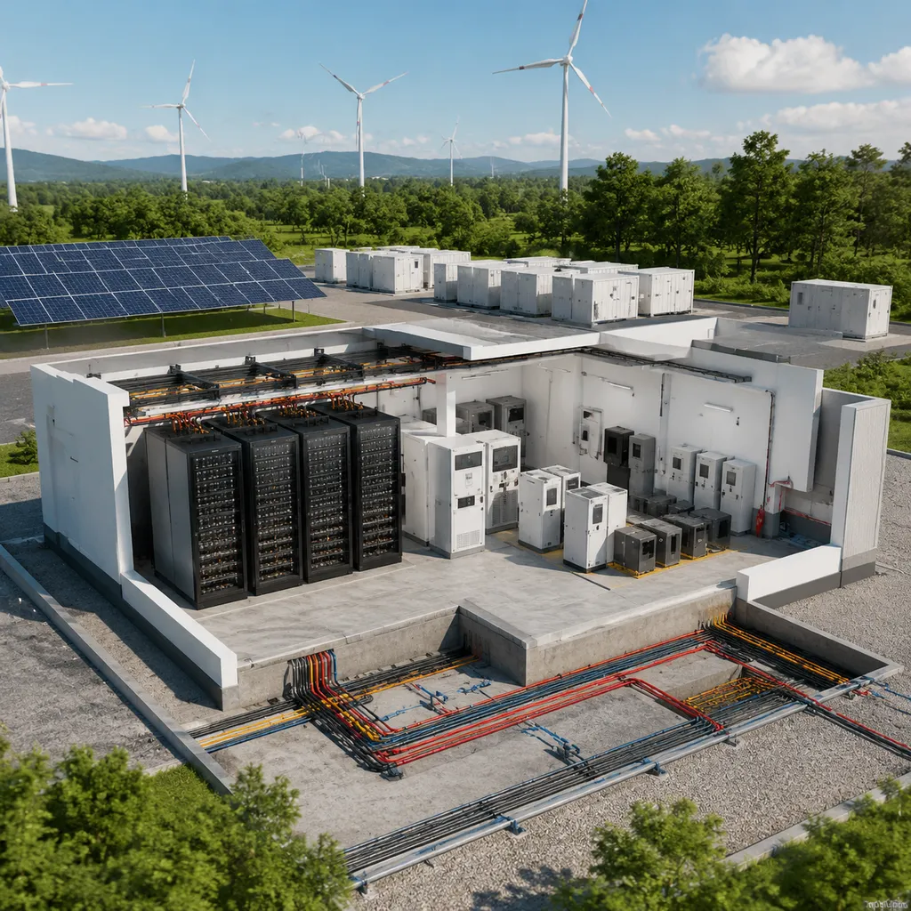
Selecting the ideal energy storage system architecture depends on site constraints, grid interconnection rules, and specific operational goals. We engineer systems across several primary topologies to maximize performance, system uptime, and long-term project value.
Centralized vs. Distributed (Modular) Architecture
- Centralized Architecture: Connects large battery arrays into a single high-capacity Power Conversion System (PCS).
- How it works: All DC battery power routes to a central inverter block before interfacing with the transformer and grid.
- Advantages: Lower initial balance-of-plant hardware cost and straightforward centralized management.
- Limitations: Higher single-point-of-failure risk; mismatch between battery strings can reduce total system yield.
- Best use cases: Large utility-scale projects with uniform charge and discharge profiles.
- Distributed or Modular Architecture: Pairs localized string inverters or converters directly with individual battery racks or modular cabinets.
- How it works: Power conversion is decentralized, managing power at the rack or cabinet level independently.
- Advantages: Eliminates single-point failures, improves string-level energy yield, and simplifies maintenance and hot-swapping.
- Limitations: Slightly higher component count and initial equipment cost.
- Best use cases: Commercial and industrial (C&I) installations and multi-stage projects requiring high availability.
Containerized Energy Storage Architecture
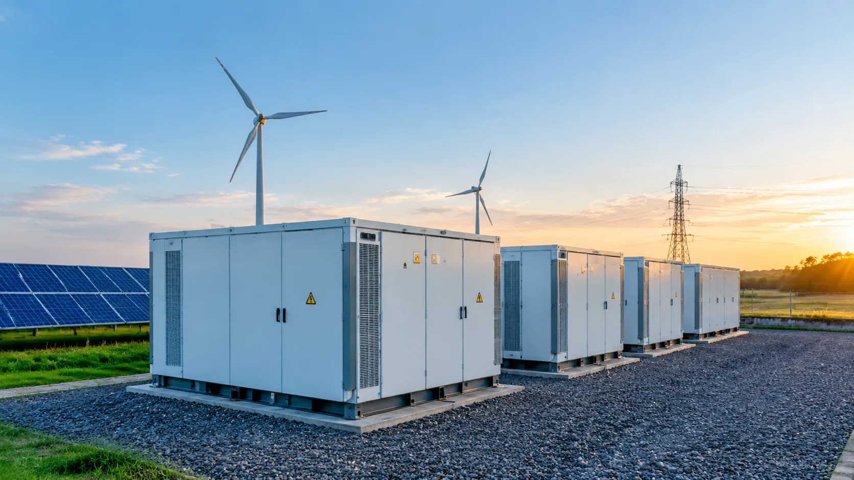
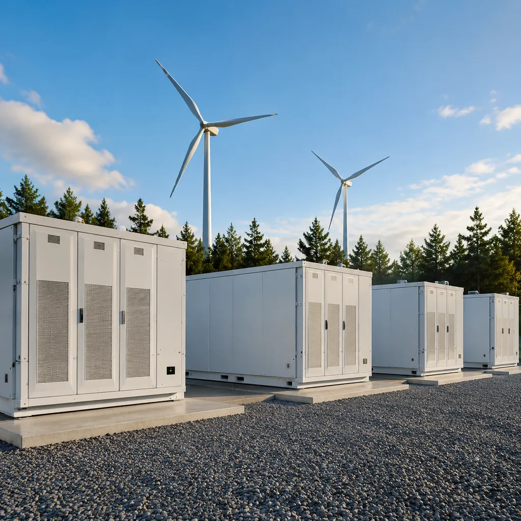
Containerized battery energy storage system topology houses battery racks, BMS, PCS, thermal management, and fire safety systems inside standardized, weather-proof enclosures.
- Standardized Deployment: Pre-engineered factory assembly minimizes site civil work, shortens installation timelines, and lowers commissioning risks.
- Space & Logistics: Standard ISO container footprints deliver high energy density in a compact area, simplifying worldwide transport and site layout.
- Modular Expansion: Deployments like our 20ft containerized battery energy storage system enable utility and industrial operators to scale capacity easily by adding parallel units over time.
AC-Coupled vs. DC-Coupled Architecture
| Feature | AC-Coupled Architecture | DC-Coupled Architecture |
|---|---|---|
| Connection Point | Shared AC bus bar via dedicated battery inverter | Shared DC bus bar before the main inverter |
| Best Application | Retrofitting existing solar or wind installations | Brand-new solar-plus-storage projects |
| Pros | Independent system operation, flexible placement, simpler retrofits | Higher round-trip efficiency, shared inverter costs, captures clipped PV energy |
| Cons | Double AC/DC conversion step increases energy losses | Complex control integration between solar MPPT and battery management |
Hybrid Architecture for Complex Sites
Hybrid energy storage system design integrates multiple energy sources—such as solar PV, wind turbines, diesel generators, and the utility grid—into a single managed power system.
- Multi-Source Dispatch: Optimizes energy flow across all connected assets in real time, maximizing renewable consumption and cutting fuel costs.
- Microgrid Capabilities: Functions as a master grid-forming voltage source, delivering seamless islanding, frequency stabilization, and black-start capabilities during main grid outages.
- Best Use Cases: Islanded microgrids, remote industrial operations, and mission-critical facilities requiring high-reliability microgrid energy storage solutions.
How to Design an Energy Storage System Step by Step
Step 1: Define Project Objectives
We start by identifying your primary operational goals:
Economic Optimization: Implementing targeted peak shaving and load shifting strategies to cut utility demand charges.
Resilience & Grid Support: Establishing emergency backup power, frequency regulation, or EV charging load buffering.
Renewable Integration: Maximizing solar self-consumption and reducing generation curtailment.
Step 2: Conduct Load Profile Analysis
A precise load profile analysis for ESS forms the baseline for system sizing. We evaluate:
Daily Demand Curves: Pinpointing peak demand windows and baseline loads across various operational shifts.
Seasonal Variability: Accounting for severe winter or summer HVAC and production consumption surges.
Critical Load Isolation: Separating essential loads requiring uninterrupted emergency backup.
Step 3: Calculate Power (kW) and Energy (kWh) Needs
We separate power capacity from energy capacity to avoid sizing mismatches:
Power Rating (kW): Dictates the instantaneous maximum output required to cap facility demand spikes.
Energy Capacity (kWh): Determines total discharge duration and sustained runtime.
Step 4: Select Battery Chemistry
We select chemistries based on thermal tolerance, degradation curves, and safety profiles. For commercial and industrial energy storage system design, LiFePO4 (LFP) is our primary choice due to its high thermal stability and 6,000+ cycle life capability.
Step 5: Select System Topology
Determining system coupling dictates how power flows through your facility electrical infrastructure:
AC-Coupling: Best for retrofit projects adding storage to pre-existing solar arrays or utility connections.
DC-Coupling: Preferred for new solar-plus-storage system design installations to minimize conversion losses.
Enclosure Layout: Modular indoor racking versus outdoor, containerized units depending on available footprint.
Step 6: Size Power Conversion System (PCS) & Inverters
Our power conversion system design matches charge and discharge requirements (C-rate). We size components to handle motor inrush currents, reduce harmonic distortion, and deliver sub-10ms response times for critical switchovers.
Step 7: Integrate Thermal Management
Uniform temperature control prevents localized cell aging. We compute localized cooling loads and implement closed-loop liquid cooling or industrial HVAC units to maintain module temperatures between 15°C and 30°C.
Step 8: Engineer Protection & Safety Systems
Multi-layer protection shields your physical assets and personnel:
Electrical Protection: High-interrupting capacity fuses, circuit breakers, and surge protection devices (SPD).
Hazard Mitigation: Pack-level off-gas sensors, clean-agent fire suppression (aerosol/Novec 1230), and structural thermal barriers.
Step 9: Configure Communication & Control Layers
We deploy standard open protocols (Modbus TCP, CAN bus, IEC 60870-5-104) across all control levels:
Battery Management System Architecture: Continuous monitoring of individual cell voltages, temperatures, and State of Charge (SOC).
EMS Integration: Real-time dispatch orchestration linked to facility SCADA and utility metering points.
Step 10: Validate Site Layout & Physical Installation
We confirm physical space constraints to streamline civil work and long-term maintenance:
| Site Requirement | Validation Focus |
|---|---|
| Spatial Clearance | Ensure required set-back distances for airflow, egress, and service access. |
| Environmental Protection | Verify NEMA 3R/4X or IP54/IP65 ratings fit local climate extremes. |
| Civil & Electrical Setup | Optimize trenching for cable routing, grounding grids, and concrete foundation pads. |
Key Design Factors That Affect ESS Performance
System Efficiency
Every power conversion step introduces energy loss. We design systems to minimize these losses and lower total operational costs:
Conversion Losses: Optimizing the power conversion system design reduces inverter, transformer, and switching losses.
Parasitic Loads: HVAC cooling, pump operation, and controller standby power consume energy. Minimizing parasitic loads directly preserves net energy output.
Target Round-Trip Efficiency (RTE): A high-performing battery energy storage system architecture targets 85% to 90%+ round-trip efficiency at the AC coupling point.
Reliability and Availability
To meet high availability targets (often >98%), the system layout must prioritize fault tolerance and fast recovery:
Redundancy: Modular N+1 architecture ensures single-component failures do not trigger full system outages.
Fault Isolation: Advanced protection logic isolates individual battery strings or inverter modules instantly when anomalies occur, keeping the rest of the system online.
Scalability and Expansion
A forward-thinking energy storage system architecture accounts for future capacity growth without requiring full system redesigns:
Parallel Expansion: Modular rack and containerized layouts allow seamless capacity scaling as site loads grow.
Future-Proofing: Sizing busbars, switchgear, and control interfaces upfront simplifies secondary physical and electrical expansions.
System Safety
Safety is non-negotiable and must be built into every hardware and software layer of a custom ESS integration project:
Thermal Runaway Prevention: Cell-level isolation and strict voltage, current, and temperature limits prevent thermal escalation.
Electrical Protection: Coordinated breakers, fuses, and rapid isolation mechanisms mitigate short circuits and arc faults.
Fire Containment: Deflagration venting and multi-stage suppression systems prevent fire propagation across racks.
Maintainability
Unscheduled downtime severely impacts project ROI. We design spatial and control layouts to make servicing straightforward:
Service Access: Generous clearance around racks, power conversion modules, and thermal units ensures safe technician access.
Component Replacement: Modular, hot-swappable components allow rapid replacement of faulty modules.
Remote Diagnostics: Cloud-based telemetry provides real-time monitoring and predictive maintenance alerts before physical failures happen.
Lifetime and Degradation
Battery life depends heavily on daily operating conditions and control strategies:
Cycle Depth (DoD): Managing charge and discharge limits slows down irreversible capacity degradation.
ESS Thermal Management: Precision liquid cooling maintains cell-to-cell temperature uniformity within a tight window, extending battery cycle life.
Active Balancing: BMS-driven active balancing balances cell voltages across all modules, maximizing usable capacity over years of continuous operation.
To evaluate technical specifications and choose the right design parameters for your site, review our detailed BESS buying guide.
Thermal Management and Safety in Energy Storage System Design
Why Thermal Design Is Critical
Temperature directly dictates lithium-ion battery health, degradation rate, and safety. Operating outside the optimal temperature window (typically 15°C to 35°C) degrades cell chemistry and impacts system ROI:
- Accelerated Capacity Loss: Continuous operation above 40°C doubles the capacity degradation rate, rapidly degrading battery state of health (SOH).
- Cell Imbalance: Thermal gradients across a rack cause cells to age unevenly. The weakest cell limits the usable capacity of the entire string.
- Thermal Runaway Risks: Uncontrolled heat build-up can trigger exothermic chemical reactions, leading to fire or explosion if heat generation exceeds dissipation capacity.
Effective ESS thermal management keeps cell-to-cell temperature variations under 3°C, extending overall system lifespan and preserving warranty terms.
Air Cooling vs. Liquid Cooling
Choosing the correct cooling topology depends on energy density, C-rate requirements, and environmental conditions.
| Feature | Air Cooling | Liquid Cooling |
|---|---|---|
| Cooling Efficiency | Moderate (air has low heat capacity) | High (coolant offers high heat transfer coefficient) |
| Temperature Uniformity | Higher temperature delta (5°C–8°C) | Strict temperature uniformity (<2°C–3°C variance) |
| Energy Density | Lower footprint efficiency | Higher energy density (up to 40% spatial savings) |
| CAPEX & OPEX | Lower initial cost, simpler maintenance | Higher upfront cost, lower parasitic fan power |
| Best Application | Low C-rate, low-density C&I applications | Grid-scale, high C-rate, containerized BESS |
We incorporate advanced liquid-cooling loops in our custom energy storage solutions to achieve maximum energy density while suppressing thermal propagation risks at the rack level.
Fire Detection and Suppression Strategy
Safety in modern energy storage system architecture relies on a multi-layer defense strategy that intervenes long before open flames appear:
- Off-Gas Detection: Early warning sensors monitor off-gassing (hydrogen, carbon monoxide, and electrolyte vapor) at the module level, triggering alerts minutes before thermal runaway occurs.
- Pack-Level Suppression: Targeted clean-agent gas (such as FK-5-1-12 / Novec 1230) or aerosol systems deploy directly inside sealed battery modules or racks.
- Emergency Shutdown Logic: Automated control flow immediately isolates the affected battery string, halts the Power Conversion System (PCS), and activates exhaust ventilation.
- Water Deluge Integration: External connections for fire department hookups ensure containment in worst-case utility-scale events.
Safety Standards and Compliance
Meeting international energy storage safety standards is non-negotiable for project bankability, permitting, and insurance coverage. We engineer all systems to meet rigorous global standards, particularly for heavy-duty deployments in industrial factory installations:
- UL 9540 / UL 9540A: Evaluates complete system safety and cell-to-cell thermal runaway fire propagation testing.
- UL 1973: Standard for stationary batteries in energy storage applications.
- IEC 62619: Global safety requirements for industrial secondary lithium cells and batteries.
- UN 38.3: Transport safety testing for lithium batteries.
- CE & ISO 9001: European compliance and quality management system verification.
Energy Storage System Design Across Applications
We tailor every energy storage system design to match the specific operational profiles and financial objectives of the site. The right energy storage system architecture directly determines system performance, cycle life, and project payback. Below is an overview of how we configure systems for different operational environments across targeted industrial and commercial applications.
| Application Profile | Primary Objective | Key Design Feature | Core Architecture Choice |
|---|---|---|---|
| C&I Peak Shaving | Lower peak demand charges | Fast response EMS dispatch | Modular indoor/outdoor BESS |
| Solar-Plus-Storage | Maximize self-consumption & limit curtailment | Integrated DC bus charging | DC-coupled topology |
| Microgrids & Backup | Uninterrupted critical load support | Sub-20ms islanding switch | Hybrid PCS with grid-forming capability |
| EV Fast Charging | Buffer high-kW power spikes | Dynamic C-rate load smoothing | Containerized BESS buffer |
| Industrial / Logistics | Maintain 24/7 power quality | High reliability & sag mitigation | Centralized or modular BESS |
| Utility & Grid-Scale | Frequency regulation & grid support | Sub-second response & SCADA control | Large containerized AC-coupled systems |
C&I Peak Shaving and Demand Charge Reduction
- Target: Commercial buildings, retail hubs, and light industrial facilities.
- Sizing Logic: Battery energy capacity (kWh) is sized based on the length and height of the daily peak demand curve (typically 2 to 4-hour discharge windows).
- Economic Value: Reduces peak monthly utility demand charges and provides targeted load shifting to capture time-of-use (TOU) price differentials.
Solar-Plus-Storage Systems
- Efficiency Focus: Utilizing a solar plus storage system design with DC coupling eliminates redundant AC-to-DC conversion steps, raising overall round-trip efficiency.
- Curtailment Prevention: Captures excess solar generation that exceeds grid export limits and stores it for evening or peak-rate dispatch.
- Export Control: Automated EMS logic manages real-time power export limits at the point of common coupling (PCC).
Microgrids and Backup Power
- Seamless Islanding: High-speed PCS controls detect grid failure and transfer to islanded mode in under 20 milliseconds without resetting sensitive equipment.
- Critical Load Support: Establishes a stable local voltage and frequency reference, allowing seamless co-generation with standby diesel generators or onsite solar.
EV Charging Infrastructure
- Grid Upgrade Deferral: Buffers sudden high-power draw spikes from ultra-fast EV chargers, bypassing expensive utility grid infrastructure upgrades.
- Power Stability: Delivers consistent, high-C-rate output during peak charging periods while recharging slowly from the grid during off-peak hours.
Industrial and Logistics Facilities
- Continuous Operations: Designed specifically for cold storage plants, automated warehouses, and continuous manufacturing lines.
- Power Quality Protection: Mitigates short-duration voltage sags, brownouts, and power harmonics that disrupt delicate automation and process machinery.
Utility and Grid-Scale Applications
- Grid-Scale Energy Storage Design: Large containerized topologies scaled from 1 MW to several hundred megawatts.
- Ancillary Services: Delivers sub-second primary frequency response, synthetic inertia, voltage regulation, and renewable smoothing to stabilize the main grid.
Common BESS Design Mistakes to Avoid
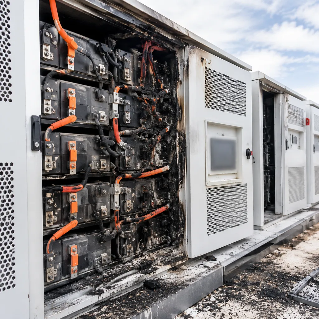
Even minor oversights in energy storage system architecture can cause severe performance bottlenecks, void warranties, or derail your return on investment. Through years of hands-on engineering, we frequently see six critical design pitfalls during system deployment.
| Design Pitfall | Operational Impact | Corrective Strategy |
|---|---|---|
| Energy-Only Sizing | System fails during high power spikes | Size both power (kW) and energy capacity (kWh) together |
| Static Data Sizing | Misses real-world demand spikes | Analyze 15-minute interval load profiles across seasons |
| Wrong Coupling Choice | High conversion loss or high retrofit cost | Use DC-coupling for new solar; AC-coupling for retrofits |
| Thermal Neglect | Accelerated degradation and safety hazards | Calculate localized cooling loads and ambient extremes |
| Siloed Control Layers | Control conflict between BMS, PCS, and EMS | Ensure unified protocol integration (Modbus TCP/CAN) |
| Tight Layouts | Expensive maintenance and zero scalability | Reserve service clearances and modular expansion space |
Sizing Energy (kWh) Without Power (kW)
A common mistake is selecting a system based solely on total energy storage capacity (kWh) while ignoring peak power output (kW). A 1,000 kWh battery rated at only 250 kW cannot sustain a 500 kW industrial surge, regardless of how long it runs. Always match discharge duration and peak power rating to your actual electrical demand.
Ignoring Load Profile Variability
Designing an energy storage system architecture using average monthly utility bills leads to inaccurate system sizing. Without analyzing high-resolution 15-minute interval load data, you risk missing brief, high-magnitude power spikes. This results in inadequate peak shaving performance and unexpected demand charges.
Mismatches in Coupling Architecture
Selecting the wrong coupling topology reduces overall round-trip efficiency:
New Solar-Plus-Storage: Forcing AC coupling adds unnecessary AC/DC conversion stages, lowering total efficiency.
Retrofit Sites: Forcing DC coupling on existing solar PV arrays requires replacing operational inverters and rewiring the DC bus.
Underestimating Thermal Management Requirements
Poor thermal design creates cell-level temperature imbalances, accelerating capacity fade and increasing thermal runaway risks. Operating outside strict thermal limits can void supplier warranties and fail international quality certifications. Always account for extreme ambient temperatures and parasitic HVAC power consumption during the layout phase.
Weak BMS, PCS, and EMS Communication
When the Battery Management System (BMS), Power Conversion System (PCS), and Energy Management System (EMS) do not coordinate seamlessly, control latency occurs. Incompatible communication protocols lead to false alarm triggers, sluggish dispatch response, and reduced system reliability.
Overlooking Service Space and Modular Expansion
Designing a footprint solely for initial equipment dimensions creates severe operational roadblocks. Inadequate clearances hamper routine maintenance, restrict airflow, and prevent future modular capacity additions. Review our technical BESS resources to optimize footprint layouts before site deployment.
How to Evaluate a High-Quality ESS Solution
Technical Evaluation Checklist
A robust energy storage system architecture must deliver predictable performance without introducing single points of failure. We use this technical checklist to vet system build quality:
| Feature Category | Key Evaluation Criteria | Engineering Focus |
|---|---|---|
| Architecture Clarity | Clear coordination between BMS, PCS, and EMS layers | Eliminates control conflicts and latency |
| Safety Design | Pack-level fire suppression, off-gas detection, thermal isolation | Compliance with UL 9540A and IEC 62619 |
| Control Compatibility | Support for open protocols (Modbus TCP, CAN, RESTful APIs) | Direct integration with local SCADA or microgrid controls |
| Thermal Performance | Liquid or optimized air cooling maintaining <3°C cell delta | Prevents accelerated cell degradation |
| Expandability | Modular container or rack design supporting parallel additions | Enables seamless future capacity expansion |
| Warranty & SLA | Capacity retention guarantee (>70% SOH) with quick service response | Guarantees long-term operational uptime |
For technical specifications on modular system components, check our detailed energy storage resources.
Commercial Evaluation Checklist
An effective energy storage system design must deliver quantifiable financial returns alongside technical reliability. We evaluate these financial metrics prior to procurement:
- Payback Period & Financial Yield: Measure utility savings—such as peak shaving, demand charge reduction, and tariff arbitrage—against initial CAPEX to establish an accurate return timeline.
- Total Cost of Ownership (TCO): Account for parasitic HVAC loads, routine maintenance, expected degradation rates, and end-of-life battery recycling costs rather than focusing solely on upfront hardware cost.
- O&M Requirements: Confirm spare parts availability, preventive maintenance schedules, and over-the-air (OTA) firmware update capabilities.
- Single-Source Accountability: Partner with vendors that offer unified warranty coverage across the battery, BMS, and PCS to prevent cross-vendor dispute loops.
To see how specialized hardware aligns with specific project goals, review our custom energy storage solutions.
Questions to Ask Before Purchase
Before signing a procurement agreement, ask your system integrator these essential questions:
- Is the system design customized to our exact load profile? Confirm that sizing is based on high-resolution demand data rather than estimated averages.
- How are BMS, PCS, and EMS control conflicts managed? Ensure logic prioritize safety overrides without causing unexpected system shut-offs.
- Are safety certification reports fully accessible? Demand full third-party test documentation for UL 9540A and UN 38.3 compliance.
- What telemetry and monitoring access is included? Verify whether 24/7 cloud monitoring, real-time alerting, and automated fault logging are standard features.
- What are the precise commissioning and support terms? Clarify responsibility for Factory Acceptance Testing (FAT), Site Acceptance Testing (SAT), and final grid connection approval.
Turnkey Engineering in Energy Storage System Design
Building a commercial or utility-scale BESS requires far more than purchasing isolated components. Turnkey engineering bridges the gap between initial concepts and fully operational assets by treating energy storage system architecture as an integrated single system.
From Assessment to Commissioning
Managing an ESS project through a single engineering partner eliminates compatibility bottlenecks and speeds up project timelines across every execution stage:
| Project Phase | Key Deliverables & Engineering Scope |
|---|---|
| 1. Site Assessment & Design | Load profile analysis, site clearance validation, and custom energy storage system design. |
| 2. Production & FAT | Hardware integration, factory acceptance testing (FAT), pre-commissioning software loading. |
| 3. Installation & Integration | Physical placement, cable routing, switchgear interfacing, and safety enclosure setup. |
| 4. Commissioning & O&M | Grid interconnection testing, control strategy tuning, active telemetry, and lifetime maintenance. |
Benefits of End-to-End Delivery
- Faster Implementation: Streamlined workflows remove vendor handoff delays and simplify procurement.
- Reduced Integration Risk: Pre-tested hardware and software prevent protocol mismatches between the BMS, PCS, and EMS.
- Single-Point Accountability: One engineering team takes full responsibility for performance guarantees, safety compliance, and warranties.
- Consistent System Performance: Unified controls optimize round-trip efficiency, charge strategies, and thermal management.
Engineering Excellence with Percenec Energy
We simplify complex deployments by delivering tailored energy storage system architecture for C&I and grid-scale projects. At Percenec Energy, our full-stack approach combines proprietary battery management system architecture with advanced energy management system software to protect your asset and maximize operational ROI. From initial load modeling to field commissioning, we engineer safe, scalable, and high-yield energy storage solutions optimized for your exact site requirements.
Frequently Asked Questions About Energy Storage System Architecture
We regularly help clients navigate the technical decisions behind deploying commercial and utility-scale projects. Here are clear, practical answers to the most common questions about energy storage system architecture and energy storage system design.
What is the difference between ESS architecture and ESS design?
- Energy Storage System Architecture: The macro-level structural framework. It defines how components (batteries, inverters, controls) connect, communicate, and interface with the grid or load (e.g., AC-coupled vs. DC-coupled, centralized vs. modular).
- Energy Storage System Design: The detailed engineering execution. This includes precise component sizing, cable routing, ESS thermal management, electrical protection schematics, structural layout, and safety compliance integration.
Which is better, AC-coupled or DC-coupled storage?
Neither is universally superior—it depends on your project's starting point:
| Feature | AC-Coupled Energy Storage | DC-Coupled Battery Storage |
|---|---|---|
| Primary Application | Retrofitting existing solar PV systems | Brand-new solar-plus-storage projects |
| System Efficiency | Lower (multiple AC/DC conversions) | Higher (direct DC charging from PV) |
| Installation Flexibility | High; can be located independently | Tied directly to the solar inverter array |
| Best Use Case | Complex microgrids & existing sites | Optimized new solar power plants |
How do BMS, PCS, and EMS work together?
A robust battery energy storage system architecture relies on a three-tier control hierarchy:
- Battery Management System (BMS): Operates at the cell and rack level to monitor voltage, temperature, and state-of-charge while enforcing hardware-level protection.
- Power Conversion System (PCS): Manages bidirectional AC/DC power flows based on real-time commands, controlling charge and discharge rates.
- Energy Management System (EMS) Software: Functions as the master brain. It analyzes external data (utility tariffs, load forecasts, grid signals) and issues high-level dispatch commands to the PCS and BMS.
What battery chemistry is most common in modern BESS projects?
Lithium Iron Phosphate (LiFePO4 / LFP) is the standard across modern BESS installations. Compared to Nickel Manganese Cobalt (NMC), LFP delivers superior thermal stability, lower thermal runaway risks, longer cycle life (up to 6,000–10,000 cycles), and better overall cost efficiency for stationary applications.
How do I size an energy storage system for my site?
System sizing requires matching two critical parameters against your site's load profile:
- Power Rating (kW/MW): The maximum instantaneous power output required to offset demand peaks or supply critical loads.
- Energy Capacity (kWh/MWh): The total energy delivered over time (Runtime = Energy / Power).
We analyze 12 months of interval load data to size both parameters accurately, preventing capital waste from oversizing or performance failure from undersizing.
What safety standards should a commercial ESS meet?
To ensure compliance and insurability, your energy storage system design must meet core battery storage safety standards:
- UL 9540 / UL 9540A: System-level safety and full-scale thermal runaway fire testing.
- UL 1973: Safety standard for stationary battery packs.
- IEC 62619 / CE: International safety requirements for industrial lithium batteries.
- NFPA 855: Standard for the installation of stationary energy storage systems.
How long does an energy storage system last?
A well-engineered system typically lasts 10 to 15 years. System longevity depends on depth of discharge (DoD), operating temperatures controlled by the thermal system, charge/discharge rates (C-rate), and proactive EMS dispatch strategies.
Can an ESS be expanded later?
Yes, provided you choose a modular energy storage system architecture upfront. Modular architectures allow parallel rack and container additions. We design our control systems with scalable energy management system software and spare switchgear capacity so future capacity additions require minimal downtime.