Formula details
Product Details
Overview
Technical Specifications Matrix for AI Data Center BESS
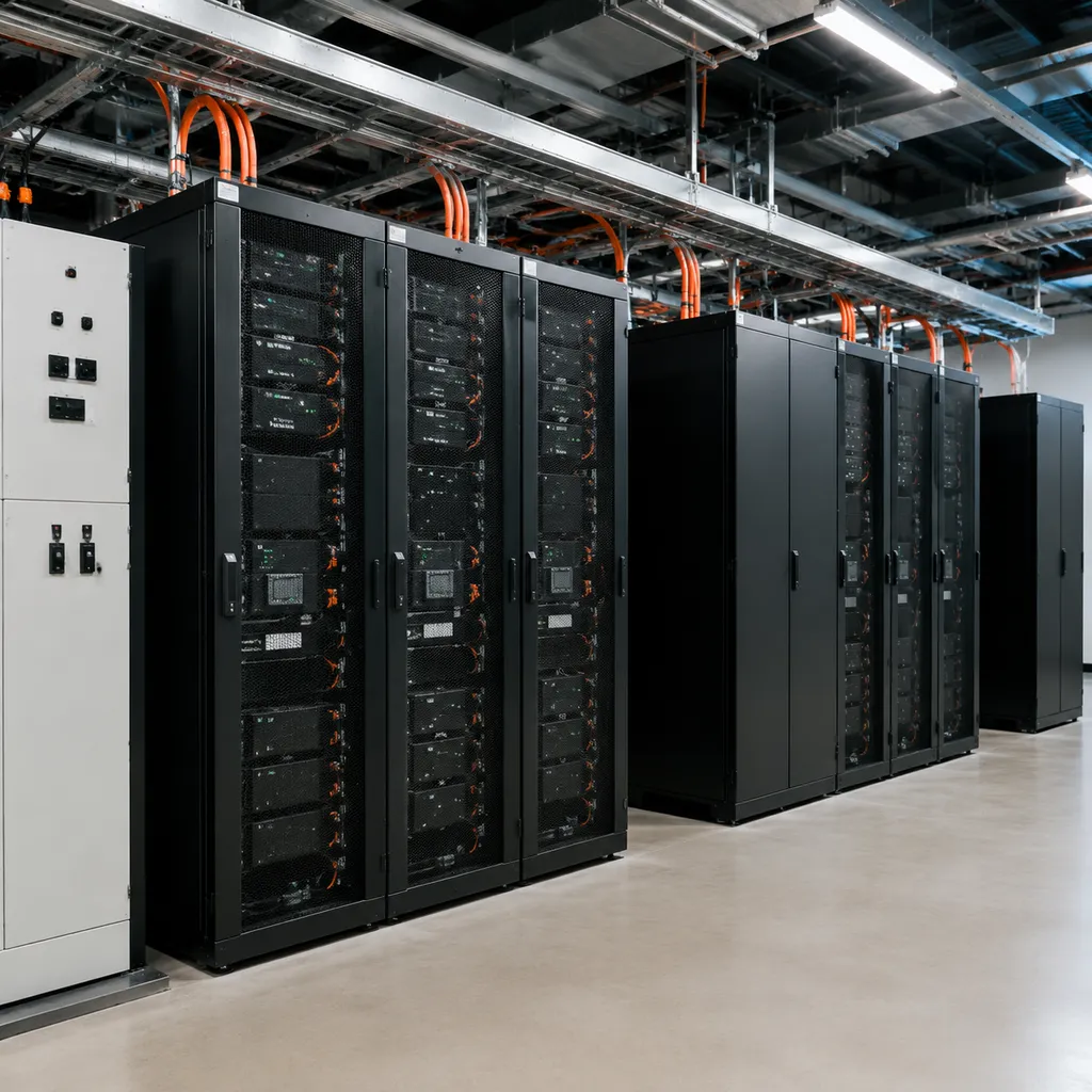
Our ai data center battery energy storage system architectures are engineered specifically to handle high-density computing environments, extreme GPU load transients, and continuous mission-critical uptime.
Application and Capacity Specifications
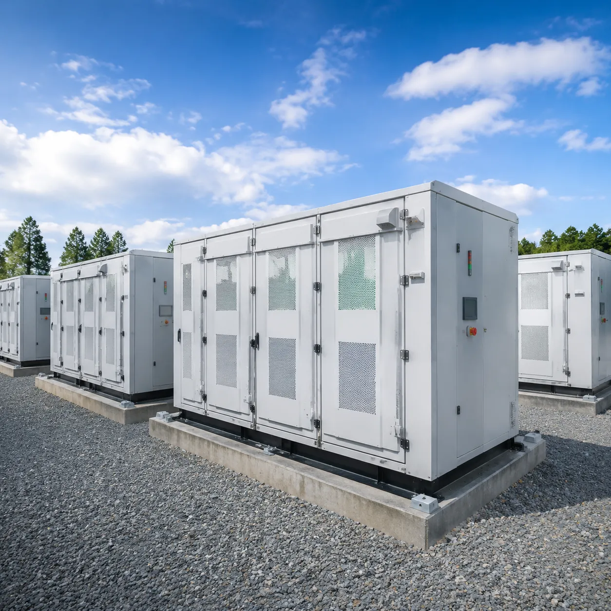
We deploy liquid-cooled storage systems configured for both edge facility applications and megawatt-scale hyperscale sites. Review our standard baseline specs or integrate our modular battery energy storage system for scalable power to fit exact site footprint constraints.
| Specification Parameter | Standard Technical Benchmark |
|---|---|
| System Energy Capacity | 1.5 MWh to 5.0+ MWh per container unit |
| Cell Chemistry | High-safety LFP (Lithium Iron Phosphate / LiFePO4) |
| Charge / Discharge Rate | 0.5C continuous to 2.0C high-rate peak response |
| Cycle Life Performance | ≥ 6,000 cycles @ 80% Depth of Discharge (DOD) |
| System Efficiency | ≥ 88% Round-Trip Efficiency (RTE) at rated AC power |
For detailed load profile evaluations and footprint calculations, refer to our BESS sizing guide.
Failover Switchover Time and System Uptime Availability
To ensure uninterrupted processing during power sags and grid interruptions, our data centre battery energy storage system utilizes real-time switchover technology and robust redundancy.
- Switchover Speed: Sub-10ms full power transfer with fast static switch integration.
- Transient Peak Response: Under 2ms dynamic response time to absorb sharp GPU power spikes.
- System Availability: Engineered for 99.999% uptime reliability across all operations.
- Redundant Architecture: N+1 auxiliary systems and dual-channel fiber communication pathways.
Cooling Method and Protection Rating
Precise temperature regulation keeps cell temperature deltas below 3°C, extending battery lifetime and maintaining peak thermal safety during rapid cycling.
- Thermal Management: Closed-loop liquid cooling with micro-channel cold plates and smart variable-speed pumping.
- Ambient Operating Range: Standard -30°C to +55°C operating environmental tolerance.
- Enclosure Rating: NEMA 3R / IP55 outer container protection with IP67-rated battery packs.
- Environmental Control: Integrated HVAC and anti-condensation humidity management.
Multi-Tier Safety & International Certification Standard
Preventative Risk Isolation
We integrate physical, thermal, and electrical barriers into every containerized unit:
- Cell-Level Thermal Barriers: Aerogel insulation sheets between cells prevent heat propagation across the module.
- Modular Structural Isolation: Fire-rated steel bulkheads isolate battery racks into independent zones.
- Fast Electrical Tripping: High-speed pyrofuses disconnect faulty strings in milliseconds to stop electrical fault propagation.
Review our comprehensive LFP battery energy storage system safety guide for a deeper look at hardware-level risk prevention.
Targeted Fire Suppression
When high-density AI loads stress power systems, active multi-stage fire protection safeguards your facility:
- Off-Gas Detection: Sensors detect trace off-gassing (electrolyte vapor, hydrogen, CO) long before smoke or heat triggers occur.
- Direct-to-Module Gas Suppression: Clean agent suppression (Novec 1230 / FK-5-1-12) injects directly into localized module spaces to extinguish fires instantly without damaging sensitive electronics.
- External Deluge Backup: Integrated water piping systems meet local fire department standards and municipal codes.
Global Regulatory Compliance
Our data centre battery energy storage system carries complete tier-1 testing credentials to streamline local AHJ permitting and utility interconnection:
- UL 9540 & UL 9540A: Full-scale fire testing proving zero thermal runaway propagation.
- UL 1973 & IEC 62619: Strict safety compliance for stationary battery packs and industrial cell designs.
- CE, UN 38.3 & ISO 9001: Certified transport safety, electromagnetic compatibility, and quality control manufacturing.
Verify our full compliance documentation and testing credentials through our international quality certifications portal.
Solving the AI Infrastructure Power Crisis
Generative AI clusters require unprecedented power density, often overwhelming existing grid capacity and traditional electrical infrastructure. Implementing an advanced ai data center battery energy storage system solves these immediate power bottlenecks, delivering high-density energy buffering, operational stability, and rapid site deployment.
Mitigating Utility Grid Interconnection Delays
Utility grid upgrades and queue approvals can delay facility energization by three to five years. Our data centre battery energy storage system bypasses grid expansion delays to accelerate your time-to-market.
- Rapid Capacity Expansion: Commission megawatt-scale AI workloads up to 24 months faster without waiting for long-lead substation transformers.
- Microgrid Co-Location: Seamlessly integrate onsite renewable generation, natural gas turbines, and limited grid feeds into a self-sufficient local power network.
- Grid-Interactive Operations: Export stored power or provide fast frequency response (FFR) to local utility networks for additional revenue.
GPU Load Smoothing & Transient Peak Management
AI training workloads create aggressive, dynamic power step-changes, causing extreme thermal stress and potential system trips across facilities.
| Operational Challenge | Battery Storage Solution | Operational Benefit |
|---|---|---|
| Dynamic GPU load ramps | Sub-millisecond active power injection | Prevents busbar voltage dips |
| Step-down transformer stress | High-density GPU load smoothing | Extends PDU and switchgear service life |
| Severe voltage flicker | Microsecond-level reactive power control | Guarantees busbar voltage stability |
Peak Shaving & Demand Surcharge Elimination
Utility demand charges and peak-hour tariffs represent a massive portion of recurring operational expenses. A targeted peak shaving energy storage system lowers utility costs while enhancing grid reliability.
- Peak Clipping: Automatically discharge stored energy when facility power draw crosses pre-set capacity thresholds, permanently flattening peak demand surcharges.
- Energy Arbitrage: Charge cell banks during low-cost off-peak hours and discharge during peak tariff cycles to drastically cut energy expenses.
- Transformer Offloading: Cap total infrastructure utilization, deferring multi-million-dollar electrical equipment upgrades.
Decarbonization & Diesel Generator Replacement
Relying purely on carbon-intensive diesel backup generators clashes with enterprise net-zero goals and strict urban emissions regulations. Transitioning to an integrated backup power battery storage system delivers clean, resilient power reserves.
- Zero-Emission Backup: Replace traditional diesel spinning reserves with instantaneous, zero-emission battery energy storage.
- Silent Emergency Power: Eliminate local air pollution, diesel fuel storage risks, and generator noise during standby testing.
- ESG Compliance: Drastically reduce Scope 1 and Scope 2 carbon emissions while maintaining 99.9999% uptime availability.
Enterprise Technical Architecture & Hardware Engineering
High-Safety Cell Chemistry (LiFePO4)
We utilize industrial-grade Lithium Iron Phosphate cells to ensure maximum thermal stability and non-propagation safety under heavy load. Explore our analysis on lithium iron phosphate safety and cycle life to see how LFP chemistry delivers over 6,000 deep-discharge cycles without performance degradation.
3-Tier Intelligent BMS Architecture
Our data centre battery energy storage system incorporates an active balancing battery management system operating across three precise levels:
Module Level (BMU): Tracks cell voltage and localized temperature with real-time active balancing.
Rack Level (RBMS): Controls string isolation, high-voltage contactors, and current limits.
System Level (SBMS): Aggregates multi-rack telemetry to optimize charge-discharge efficiency.
Smart Liquid Cooling Thermal Management
Our liquid-cooled containerized system maintains uniform thermal distribution across every module, keeping cell-to-cell temperature variance within 3°C. This precision cooling eliminates thermal throttling and guarantees maximum continuous output during rapid GPU power surges.
AI-Driven Cloud-Edge EMS
Our cloud-edge EMS pairs local sub-millisecond control with predictive cloud modeling. Learn more about our custom BMS and EMS integration to understand how our software interface directly synchronizes with facility management platforms.
| System Layer | Hardware Specification | Data Center Operational Impact |
|---|---|---|
| Cell Chemistry | Premium LiFePO4 (LFP) | High thermal run-away threshold & extended lifespan |
| BMS Control | 3-Tier active balancing | Maximizes usable capacity and prevents cell drift |
| Thermal System | Direct liquid cooling | Maintains module temperature variance ≤ 3°C |
| Control Layer | Edge-enabled AI EMS | Sub-second response to microgrid and GPU load shifts |
Turnkey 6-Phase Deployment Framework
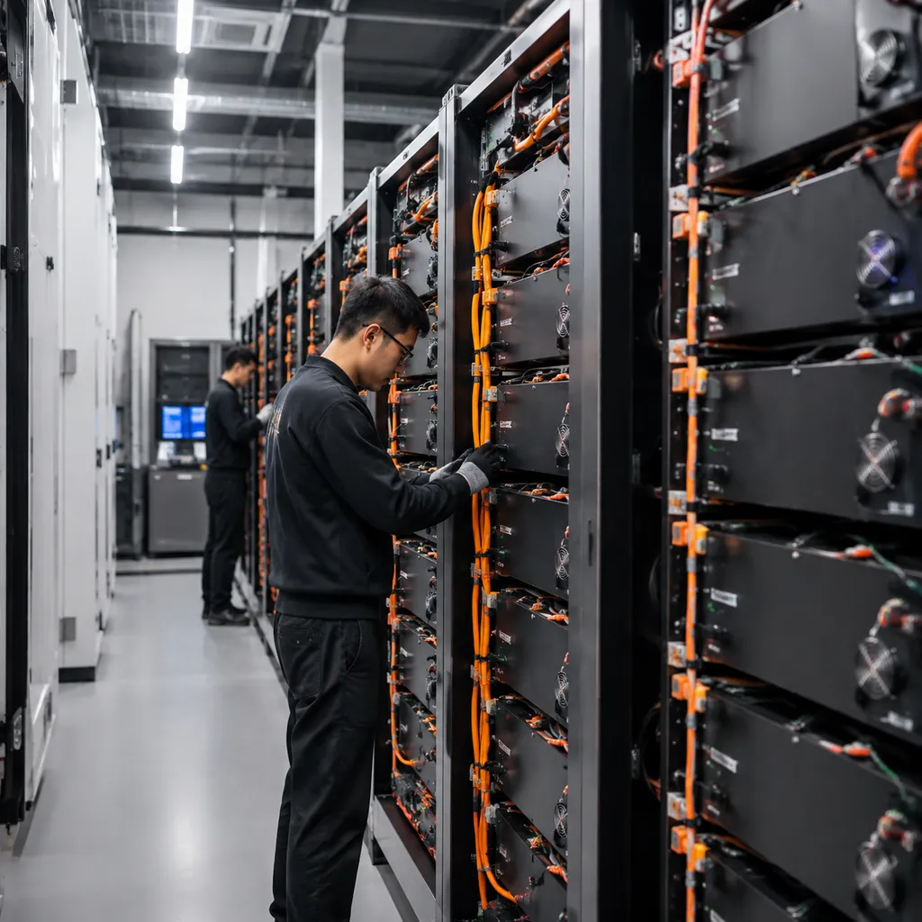
Phase 1: Site Load Curve & Power Quality Assessment
We analyze high-resolution power profiles and transient load spikes across your facility.
- Data Logging: High-frequency recording of GPU cluster power surges and harmonic distortion.
- Grid Capacity Audit: Identification of local utility transformer limits and feeder constraints.
- Power Quality Mapping: Measurement of voltage sags, power factor, and frequency stability.
Phase 2: Custom Engineering Blueprint & Financial ROI Sizing
We engineer high-performance data center BESS solutions tailored to your specific power capacity and footprint constraints.
- Capacity Optimization: Sizing megawatt-hour energy storage to handle peak shaving and emergency failover.
- Electrical & Structural Layout: CAD design covering inverter placement, switchgear integration, and fire barrier spacing.
- Financial Modeling: Detailed projections of demand charge savings, peak-shaving revenue, and ROI timelines.
Phase 3: Automated Manufacturing & Factory Acceptance Testing (FAT)
Every data centre battery energy storage system undergoes strict quality control at our automated manufacturing facilities before dispatch.
- Module & Rack Assembly: Precision integration of LiFePO4 cells, active BMS hardware, and liquid cooling lines.
- Factory Acceptance Testing (FAT): Full-power thermal run-ins, fault simulation, and capacity verification.
- Safety Pre-Certification: Rigorous isolation tests and sensor calibration prior to shipping.
Phase 4: Field Delivery, Structural Anchoring, & Grid Interconnection
We manage site logistics and physical positioning for containerized microgrid energy storage system deployments.
- Logistics & Pad Placement: Heavy-lift transport, foundation pad anchoring, and seismic securing.
- Interconnection Wiring: Medium-voltage AC/DC cabling, transformer tie-ins, and redundant communications wiring.
- Grid-Interactive Compliance: Alignment with utility interconnection rules and local code enforcement.
Phase 5: Site Acceptance Testing (SAT) & System Commissioning
We conduct rigorous field validation to guarantee instant failover and dynamic load response.
- Site Acceptance Testing (SAT): Cold-start testing, full-load charge/discharge cycles, and thermal imaging audits.
- Ultra-Fast Switchover Validation: Real-world failover drills to ensure zero interruption to active AI workloads.
- Safety System Commissioning: Operational testing of gas detection, aerosol suppression, and emergency power-off (EPO) circuits.
Phase 6: 24/7 Remote Monitoring, Predictive Maintenance, & O&M Support
We deliver continuous operational oversight utilizing our advanced real-time energy management solution to maximize uptime.
- Cloud-Edge Telemetry: Continuous cell-level voltage, temperature, and state-of-health tracking.
- Predictive Diagnostics: AI algorithms detecting thermal anomalies or capacity degradation before failures occur.
- Lifecycle O&M: Dedicated engineering support, scheduled preventative maintenance, and rapid-response SLAs.
Financial Performance & ROI Projections

Average Energy Cost Reduction
We configure our outdoor battery energy storage system with LiFePO4 battery technology to execute automated energy arbitrage. The system charges during low-cost off-peak hours and discharges during peak tariff windows, driving down overall electricity expenditure by 15% to 30% annually.
- Time-of-Use (TOU) Optimization: Automated cycling shifts major energy loads away from peak tariff rates.
- Grid Interaction: Intelligent algorithms monitor real-time spot market pricing to maximize discharge value.
Demand Charge Savings
AI cluster training generates sudden power spikes that trigger severe utility demand surcharges. Our data center BESS solutions absorb these transient GPU load surges instantaneously, establishing a firm capacity cap.
- Peak Shaving: Limits peak kW consumption to maintain utility baseline agreements.
- Surcharge Elimination: Cuts monthly demand charges by 30% to 50%, yielding substantial operational savings for high-density facilities.
Substation & Grid Infrastructure Deferral
Expanding facility load often forces expensive utility grid upgrades and transformer replacements. Integrating our microgrid energy storage solutions bridges localized power gaps without waiting years for utility interconnection expansion.
- CapEx Avoidance: Defers multi-million-dollar substation and utility feed upgrades by supplementing grid capacity on-site.
- Accelerated Time-to-Market: Allows data centers to bring new GPU racks online immediately despite physical grid limitations.
Typical Payback Window
Our enterprise-grade data centre battery energy storage system architectures deliver rapid financial returns through stacked revenue streams and cost-avoidance benefits.
| Metric | Financial Target | Primary Driver |
|---|---|---|
| CapEx Payback Period | 2.5 – 4.0 Years | Peak shaving, demand charge cuts, TOU arbitrage |
| Demand Surcharge Reduction | Up to 50% | Automated load smoothing during AI cluster runs |
| OpEx Reduction | 15% – 30% | Off-peak charging and optimized dispatch cycles |
| Asset Lifetime Return (IRR) | 18% – 25% | 15+ year operational life with minimal degradation |
Enterprise Data Center BESS FAQ
How does a BESS differ from standard short-duration data center UPS systems?
Traditional UPS setups offer 5 to 15 minutes of backup runtime—just enough to bridge the gap until diesel generators kick in. In contrast, a data centre battery energy storage system provides multi-hour energy capacity (typically 2 to 4+ hours) combined with active energy management. Beyond emergency failover, we design our BESS for continuous operation, enabling daily peak shaving, demand charge mitigation, and revenue-generating grid services. To evaluate the ideal capacity and setup for your facility, check out our comprehensive data center BESS buying guide.
Can Percenec Energy BESS integrate with our existing facility management software?
Yes. We build our ai data center battery energy storage system hardware with open industrial communication standards, including Modbus TCP/IP, CAN bus, and RESTful APIs. This ensures seamless protocol handshakes with your existing Building Management System (BMS), DCIM software, or SCADA infrastructure. Your facility managers get full real-time telemetry, automated dispatch, and centralized power orchestration without changing software ecosystems. For specific integration protocols, browse our data center storage FAQ page.
How does the system handle rapid, high-amplitude GPU power fluctuations?
Generative AI training and inferencing workloads create extreme, sub-second power spikes that severely stress utility transformers. Our BESS integrates ultra-fast smart power inverters coupled with millisecond-level Energy Management System (EMS) response. By immediately injecting or absorbing power during step-load changes, the system delivers high-density GPU load smoothing, holding utility power draw steady and preventing localized voltage sags.