Formula details
Product Details
Overview
1 MW Battery Energy Storage System (BESS)
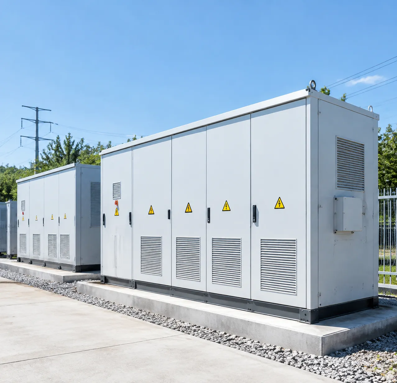
A 1 MW battery energy storage system (BESS) is an industrial-grade energy storage solution engineered to deliver up to 1 megawatt of instantaneous electrical power.
1 MW BESS System Topology
Battery Racks
↓
DC Bus (600–1500 V)
↓
Bi-Directional PCS
↓
Transformer
↓
Medium-Voltage Distribution
↓
Grid / Plant Load
Multi-Tier BMS → Site EMS Controller → System Monitoring & Control
Power Rating vs. Energy Capacity (MW vs. MWh)
Understanding the distinction between power (megawatts, MW) and energy (megawatt-hours, MWh) is fundamental when sizing your commercial battery energy storage system:
- Power (1 MW): The maximum instantaneous discharge rate the system can deliver at any single moment.
- Capacity (MWh): The total amount of stored energy available over a sustained duration.
| Configuration | Continuous Output | Discharge Duration | Primary Applications |
|---|---|---|---|
| 1 MW / 1 MWh (1C) | 1,000 kW | 1 Hour | Fast frequency response, short-duration peak mitigation |
| 1 MW / 2 MWh (0.5C) | 1,000 kW | 2 Hours | Industrial demand charge management, solar smoothing |
| 1 MW / 4 MWh (0.25C) | 1,000 kW | 4 Hours | Long-duration energy arbitrage, microgrid resilience, utility deferral |
Standard Containerized Modular Design
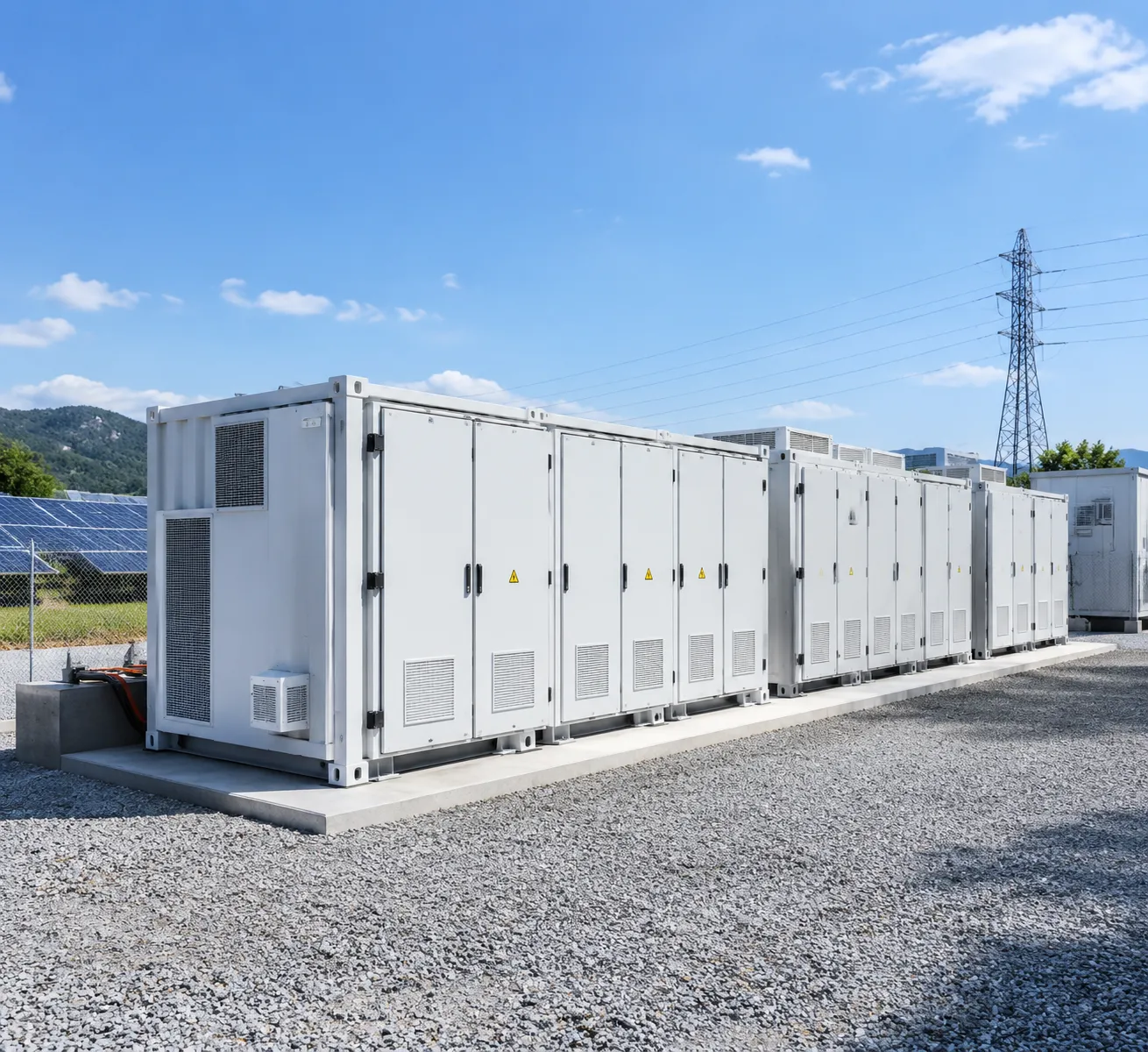
We house our systems in standardized, weather-sealed ISO shipping containers. This modular design delivers turnkey, plug-and-play installation, simplified shipping logistics, and rapid on-site commissioning.
20-ft ISO Container Layout Overview
HVAC / Thermal Management
↓
High-Density DC Battery Racks
LFP Modules + Rack-Level BMS
↓
PCS / Control / EMS
Integrated Safety Systems:
Fire Suppression (Aerosol / Clean Agent) → Gas Detection & Deflagration Vents
- 20-Foot ISO Containers: Ideal for space-constrained industrial footprints. Typically configured for 1 MW / 1 MWh to 1 MW / 2 MWh setups, housing high-density racks, integrated HVAC/liquid chillers, and fire suppression systems.
- 40-Foot ISO Containers: Engineered for high-capacity projects ranging from 1 MW / 3 MWh to 1 MW / 4 MWh+. These enclosures accommodate larger cell volumes, centralized power conversion systems (PCS), and dedicated walk-in maintenance corridors.
Battery Chemistry Comparison
Selecting the correct cell chemistry dictates your system's footprint, thermal stability, operational life cycle, and Levelized Cost of Storage (LCOS).
SAFETY & CYCLE LIFE ENERGY DENSITY DISCHARGE DURATION
| Specification | Lithium Iron Phosphate (LiFePO4 / LFP) | Nickel Manganese Cobalt (NMC) | Vanadium Redox Flow (VRFB) |
|---|---|---|---|
| Thermal Stability | Exceptional (High thermal runaway threshold) | Moderate (Requires active liquid cooling) | Inherent (Aqueous, non-flammable) |
| Cycle Life (80% DoD) | 6,000 – 10,000+ cycles | 3,000 – 4,500 cycles | 15,000 – 20,000+ cycles |
| Footprint Efficiency | High | Very High | Low (Large tank footprint) |
| Industry Standard | Primary choice for C&I/Utility | Specialized / Space-limited sites | Long-duration stationary storage |
Operational Modes: Grid-Tied, Off-Grid, and Hybrid
Our 1 MW containerized energy storage platforms operate across multiple structural grid modes:
- Grid-Tied Mode: Operates synchronously with the local utility network to execute automated peak shaving, frequency regulation, voltage support, and time-of-use (TOU) energy arbitrage.
- Off-Grid (Islanding) Mode: Forms an independent voltage and frequency reference using advanced grid-forming inverters, supplying continuous power to remote facilities, mining operations, or isolated sites.
- Hybrid Mode: Continuously tracks grid health and provides seamless, microsecond-level transfer between grid-tied operation and islanded microgrid backup during blackouts and brownouts.
Core Components of a 1 MW Battery Storage Container
1. High-Density Battery Racks and Multi-Tier BMS
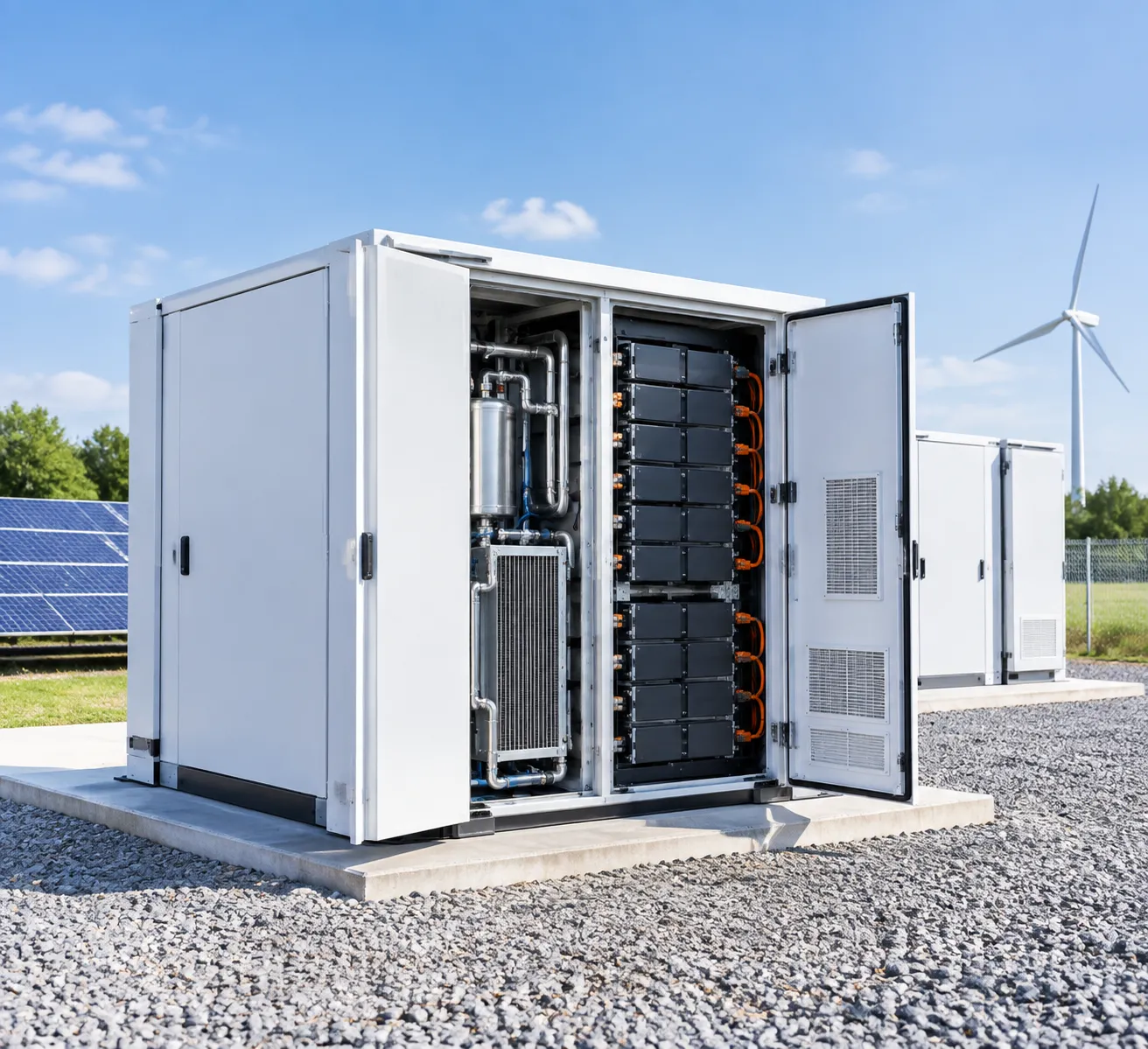
The energy core consists of modular battery racks populated with high-capacity cells. We utilize a three-tier Battery Management System (BMS) architecture:
Cell Level (BMU): Monitors individual cell voltage and real-time temperatures.
Rack Level (RBMS): Balances string voltages and manages rack-level contactors.
System Level (SBMS): Aggregates total DC bus data, communicates with the inverter, and optimizes overall lithium iron phosphate battery system safety and cycle life.
2. Bi-Directional Power Conversion System (PCS) and Smart Inverters
The 1 MW power conversion system PCS manages seamless AC-to-DC charging and DC-to-AC discharging. Key attributes include:
Four-Quadrant Operation: Delivers active power control (P) and reactive power support (Q) for power factor correction.
Grid-Forming & Grid-Following Modes: Enables black-start capability during outages and rapid response during grid-connected operation.
Sub-Cycle Switching: Ensures near-instantaneous transition speeds under 20 milliseconds during grid disturbances.
3. Energy Management System (EMS) Software for Automated Dispatch
The energy management system EMS software serves as the digital brain of the installation. It runs automated control algorithms that handle:
Dynamic Peak Shaving: Automatically discharges storage when facility demand approaches expensive tariff thresholds.
Time-of-Use (TOU) Arbitrage: Charges the system during low-rate off-peak periods and dispatches during peak utility windows.
SCADA Integration: Supports industry protocols (Modbus TCP/IP, DNP3, IEC 61850) for local controls and remote cloud fleet monitoring.
4. Thermal Management: Liquid Cooling vs. Forced-Air HVAC
Maintaining uniform cell temperature is critical to prevent premature degradation and ensure operational safety.
| Feature | Liquid-Cooled Battery Container | Forced-Air HVAC System |
|---|---|---|
| Temperature Uniformity | Cell delta-T ≤ 2.5°C to 3°C | Cell delta-T ≤ 5°C to 8°C |
| Energy Consumption | Up to 30% lower auxiliary power load | Higher parasitic load in extreme climates |
| System Footprint | Higher energy density; compact layout | Requires dedicated airflow clearance channels |
| Maintenance Profile | Coolant loop checks and pump inspection | Regular filter replacements and compressor service |
5. Multi-Layered Safety and Fire Protection
To maintain full NFPA 855 fire suppression energy storage compliance, our container designs incorporate rigorous hazard mitigation:
Early Gas & Off-Gas Detection: Multi-sensor arrays identify hydrogen and carbon monoxide releases prior to any thermal event.
Clean Agent Fire Suppression: Total flooding systems (such as Novec 1230 or FM-200) paired with targeted water mist systems.
Deflagration Venting: Certified explosion relief roof panels direct pressure upward and away from personnel and surrounding infrastructure.
Key Applications for a 1 MW Battery Energy Storage System
Peak Shaving and Demand Charge Reduction
For energy-intensive manufacturing plants and industrial facilities, utility demand charges can account for up to 50% of the total monthly electricity bill. A peak shaving battery system automatically discharges when facility power consumption approaches preset threshold limits. By clipping these high-kW peaks, you avoid expensive tariff brackets without altering daily production schedules.
Solar-Plus-Storage and Wind Farm Energy Shifting
Intermittent renewable generation often leads to curtailment during peak production hours. Integrating a 1 MW system allows developers to store excess generation and inject power back into the grid when spot market prices peak. Our utility-scale battery storage containers for solar and wind smooth output fluctuations and maximize total kilowatt-hour monetization.
| Application | Primary Economic & Operational Benefit |
|---|---|
| Peak Shaving | 20%–40% reduction in utility demand charges |
| Renewable Firming | Zero curtailment; optimized Time-of-Use arbitrage |
| Microgrid Islanding | Uninterrupted operations during grid outages |
| Ancillary Grid Services | Capacity payments for frequency/voltage response |
| EV Fleet Management | Eliminates grid upgrade costs for DC fast chargers |
Emergency Backup Power and Microgrid Islanding
When grid reliability falters, an industrial BESS solution provides critical resilience. Working alongside on-site generation, the system switches to microgrid islanding battery storage mode in milliseconds, maintaining stable voltage and frequency for critical loads. Implementing commercial and industrial backup power systems prevents costly downtime, equipment damage, and product loss during extended blackouts.
Grid Ancillary Services
A commercial battery energy storage system provides sub-second response times, making it ideal for lucrative grid-support programs:
Frequency Regulation: Rapid bi-directional charge/discharge to balance grid frequency deviations.
Voltage Support: Dynamic reactive power (VAR) injection to stabilize local distribution lines.
Spinning Reserves: Standing by as fast-acting capacity without the emissions of idling thermal turbines.
EV Fleet Charging Infrastructure Demand Management
Electrifying commercial vehicle fleets creates massive, intermittent electrical loads from multi-megawatt DC fast-charging hubs. A 1 MW BESS acts as a power buffer, absorbing grid electricity during off-peak periods and discharging during simultaneous vehicle charging events to prevent severe transformer overloads and expensive utility infrastructure upgrades.
1 MW BESS Cost Breakdown and ROI Factors
Investing in a 1 MW battery energy storage system requires balancing upfront capital expenditure (CapEx) against lifetime operational costs (OpEx) to build a clear, bankable business case. When we design and deploy utility-grade and industrial storage, we calculate total cost of ownership (TCO) based on hardware selection, installation scope, and local market revenue streams.
Upfront CapEx: System Hardware and EPC Integration
The upfront cost of a complete 1 MW BESS generally breaks down into four main buckets:
| CapEx Component | Typical Share | Key Cost Drivers |
|---|---|---|
| Battery Racks & DC Block | 45% – 55% | Lithium iron phosphate (LFP) cell pricing, integrated multi-level BMS, rack enclosure |
| Power Conversion System (PCS) | 12% – 18% | Bi-directional smart inverters, medium-voltage step-up transformer, switchgear |
| Balance of System (BOS) | 10% – 15% | Liquid cooling/HVAC, fire detection & clean agent suppression, container enclosure |
| EPC, Civil Works & Interconnection | 20% – 25% | Foundation pads, trenching, utility studies, permitting, and grid-tie commissioning |
Choosing a standardized modular battery energy storage system for scalable power significantly cuts on-site civil works and commissioning labor compared to custom-built DC field arrays.
Ongoing OpEx: Maintenance, Auxiliary Draw, and Warranties
Operational expenses dictate your net system margins over a 10- to 15-year asset lifecycle:
- Preventative Maintenance: Biannual filter swaps, coolant loop inspections, torque checks, and firmware validation.
- Auxiliary Parasitic Loads: Continuous power draw from thermal management (liquid chillers or HVAC) and system controls, typically accounting for 1% to 3% of system capacity.
- Extended Warranties & Service Agreements: Performance guarantees securing State of Health (SOH) thresholds and capacity replenishment.
Revenue Streams and Payback Timeline
A well-sited commercial battery energy storage system generates returns across multiple value stacks simultaneously:
- Peak Shaving & Demand Charge Management: Capping facility peak kW during high-tariff windows delivers immediate, recurring utility bill savings.
- Energy Arbitrage: Charging during off-peak hours (or storing surplus on-site solar) and discharging during peak rate windows.
- Grid Services & Demand Response: Participating in capacity markets, frequency regulation, and automated demand response programs with grid operators.
For high-utilization commercial and industrial sites deploying a factory-integrated turnkey LiFePO4 BESS, average project payback typically ranges from 3.5 to 7 years, depending on regional utility tariff structures and operational hours.
Tax Credits, Depreciation, and Financial Incentives
Federal and regional clean energy policies can offset 30% to 50% of the total installed 1 MW BESS cost:
- Clean Energy Investment Tax Credits (ITC): Substantial base tax credits for standalone storage and solar-plus-storage projects.
- Modified Accelerated Cost Recovery System (MACRS): Allows accelerated 5-year depreciation schedules to front-load tax savings.
- Regional Grants & Grid Modernization Rebates: State-level and utility-specific energy resilience incentives that directly reduce net equipment costs.
Critical Technical Specifications to Evaluate Before Buying
| Technical Parameter | Standard Specification | Performance Benchmark |
|---|---|---|
| Discharge Duration / C-Rate | 0.5C (2-Hour) or 0.25C (4-Hour) | 1 MW / 2 MWh to 1 MW / 4 MWh configurations |
| Round-Trip Efficiency (RTE) | ≥ 86% – 90% (AC-to-AC) | Minimizes parasitic and auxiliary conversion losses |
| Depth of Discharge (DoD) | 90% – 100% usable capacity | Maximizes usable energy while preserving cell life |
| Cycle Life & Degradation | 6,000 to 8,000 cycles | Retains ≥ 70% to 80% State of Health (SOH) at end-of-life |
| Core Certifications | UL 9540, UL 9540A, UL 1973 | Mandated for safety, fire compliance, and permitting |
| Grid Interconnection Code | IEEE 1547 / UL 1741-SB | Complies with utility anti-islanding and smart inverter rules |
Discharge Duration and C-Rate Selection
Your operational profile determines whether a 2-hour (0.5C) or 4-hour (0.25C) containerized setup is required:
0.5C (1 MW / 2 MWh): Optimized for industrial peak shaving, fast-response frequency regulation, and dynamic demand charge management.
0.25C (1 MW / 4 MWh): Built for renewable energy time-shifting, wholesale energy arbitrage, and extended backup power during grid outages. For full sizing checklists, refer to our comprehensive BESS buying guide.
Efficiency, Degradation, and Safety Standards
- System Efficiency (RTE): We track AC-to-AC round-trip efficiency, factoring in losses across the bidirectional inverter (PCS), step-up transformer, and auxiliary cooling system. High-efficiency liquid cooling maintains thermal uniformity across all racks, keeping RTE consistently high.
- Cycle Life & SOH Warranties: Quality lithium iron phosphate (LFP) cells deliver over 6,000 cycles under standard charge/discharge profiles. We require linear capacity warranty coverage guaranteeing at least 70% to 80% retained State of Health (SOH) over 10 to 15 years.
- Grid Codes and Safety Compliance: Rapid permitting and utility approval require full alignment with recognized quality certifications, including UL 9540 for the integrated system, UL 9540A for large-scale fire and thermal runaway testing, UL 1973 for battery packs, and IEEE 1547 for grid-interconnection capabilities.
Site Requirements, Installation, and Commissioning for a 1 MW BESS
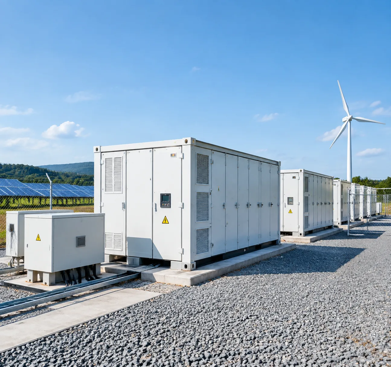
Foundation, Civil Works, and Setback Spacing
A standard utility-scale energy storage container demands a stable structural foundation and strict spatial clearances to meet local zoning and fire codes:
- Foundation Pad: Reinforced concrete slab (minimum 4,000 PSI) engineered to support enclosure weights between 30 and 45 metric tons.
- Environmental Setbacks: Standard NFPA 855 fire suppression energy storage spacing requires at least 10 feet (3 meters) of clearance from lot lines, public ways, and external structures.
- Drainage and Containment: Secondary containment trenches designed for coolant management and stormwater runoff.
| Parameter | Requirement for 1 MW Container | Purpose |
|---|---|---|
| Slab Thickness | 12 to 18 inches reinforced | Structural load distribution |
| Setback Buffer | 10 ft (3 m) standard clearance | Fire access & thermal isolation |
| Crane Access | 50-ton mobile crane clearance | Safe offloading and rigging |
Medium-Voltage Interconnection and Switchgear
To connect a 1 MW unit to commercial feeders or utility lines, our systems utilize dedicated balance-of-plant electrical infrastructure:
- Step-Up Transformer: Dry-type or liquid-filled transformers stepping low-voltage output (typically 480V or 690V from the PCS) up to medium-voltage distribution levels (11kV to 34.5kV).
- Switchgear Protection: Integrated medium-voltage breakers, protective relays, and disconnect switches with real-time fault isolation.
- Grounding Grid: Low-impedance earth grounding field (<5 ohms) ensuring surge protection and personnel safety across all high-voltage equipment.
FAT vs. SAT Quality Validation
We subject every commercial battery energy storage system to a dual-stage acceptance framework before commercial operation. As seen across leading utility-scale battery storage providers compared in the industry, rigorous field validation is critical to prevent grid-connection delays.
- Factory Acceptance Testing (FAT): Fully integrated testing at our manufacturing facility, including full-power thermal runs, insulation resistance checks, BMS-to-PCS communication tests, and emergency shutdown validation.
- Site Acceptance Testing (SAT): On-site dynamic testing post-installation, verifying transformer phasing, energy management system EMS software dispatch latency, charge/discharge capacity verification, and islanding transitions.
Permitting, Interconnection Agreements, and AHJ Sign-Offs
Securing regulatory approvals involves a clear, sequential path:
- Utility Interconnection Agreement: Completing standard impact studies and securing Permission to Operate (PTO) under relevant IEEE grid-support guidelines.
- AHJ Compliance: Delivering comprehensive technical packages to the Authority Having Jurisdiction (AHJ), including UL 9540 certified energy storage documentation, UL 9540A large-scale fire test reports, and emergency response plans.
- Final Sign-Off: Conducting on-site walk-throughs with local fire marshals and municipal electrical inspectors to clear all operational permits.
Maintenance, Monitoring, and Degradation Management for a 1 MW BESS
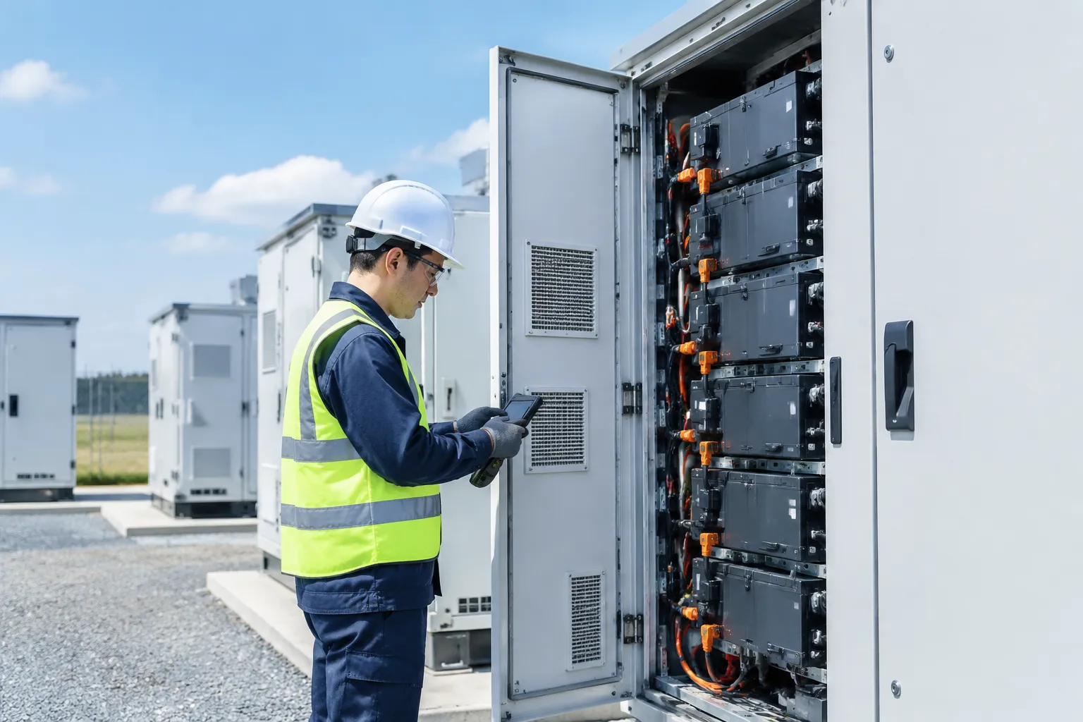
24/7 Cloud SCADA and AI-Driven Predictive Maintenance
We integrate cloud-connected SCADA platforms that stream cell-level telemetry around the clock. By combining automated fault detection with AI-driven analytics, operators can track voltage variations, state of charge (SOC), and temperature profiles in real time. Deploying an advanced factory energy management solution for real-time monitoring allows site managers to catch thermal anomalies or impedance spikes early, resolving issues before they trigger unscheduled downtime or system trips.
Active Cell Balancing and Thermal Uniformity Control
Uneven operating temperatures accelerate capacity fade across battery strings. We use intelligent thermal management paired with active balancing to keep rack performance uniform:
Thermal Delta Control: Liquid cooling keeps cell-to-cell temperature differentials within ±2°C, eliminating hot spots across high-density racks.
Active Balancing: Redistributes charge between unmatched cells during both charge and discharge cycles, preserving usable system capacity without bleeding excess power as waste heat.
Degradation Optimization: Minimizes localized stress, protecting long-term battery state of health degradation curves.
Battery Augmentation Strategies
As a containerized energy storage system approaches mid-life (typically year 7 to 10), capacity naturally degrades to 70–80% of its initial rating. Instead of overbuilding initial battery racks—which increases upfront CapEx—we utilize planned battery augmentation:
AC-Coupled Paralleling: Adding separate modular DC enclosures tied to the main AC bus to restore nominal capacity without replacing existing strings.
DC-to-DC Integration: Integrating new battery blocks via dedicated DC-DC converters to prevent circulating currents caused by voltage mismatches between aged and new cell chemistries.
Decommissioning and Recycling Protocols
End-of-life planning ensures full compliance with local environmental regulations and recovery mandates:
Safe De-energization: Certified technicians disconnect medium-voltage step-up equipment, discharge racks to safe transport levels, and isolate power conversion units.
Material Reclamation: Lithium Iron Phosphate (LFP) modules are processed through licensed recycling channels to recover high-value raw materials—including copper, aluminum, and graphite—closing the loop on material sustainability.
Frequently Asked Questions About 1 MW Battery Storage Systems
How much does a turnkey 1 MW battery energy storage system cost?
A turnkey 1 MW battery energy storage system generally ranges from $350,000 to $800,000+, depending primarily on energy capacity (discharge duration), chemistry, and site integration requirements.
- 1 MW / 2 MWh setup (2-hour duration): Typically costs between $450,000 and $650,000 for equipment, balance of system (BOS), and standard commissioning.
- 1 MW / 4 MWh setup (4-hour duration): Ranges from $750,000 to over $1,100,000 due to the doubled battery rack density.
- Additional site costs: Civil works, transformer step-up interconnections, and local utility permitting can add 15% to 25% to the total capital expenditure.
You can review our detailed battery energy storage system container specifications to evaluate complete hardware and enclosure options.
How long can a 1 MW battery power a facility during an outage?
Discharge duration depends entirely on your system’s total megawatt-hour (MWh) storage capacity and actual facility load:
- At full 1 MW peak output: A 2 MWh system delivers 2 hours of continuous backup; a 4 MWh system delivers 4 hours.
- At reduced partial load: If your facility only draws 500 kW during critical islanding operations, a 1 MW / 2 MWh system will sustain operations for approximately 4 hours.
What is the physical footprint required for a 1 MW containerized unit?
We house standard 1 MW systems in either a 20-foot or 40-foot standard ISO shipping container:
| Configuration | Container Size (L x W x H) | Base Footprint | Clear Spacing Required (NFPA 855) |
|---|---|---|---|
| 1 MW / 1–2 MWh | 20 ft × 8 ft × 8.5 ft (6.1m × 2.4m × 2.6m) | ~160 sq. ft | 10 ft (3.05 m) perimeter setback |
| 1 MW / 3–4 MWh | 40 ft × 8 ft × 9.5 ft (12.2m × 2.4m × 2.9m) | ~320 sq. ft | 10 ft (3.05 m) perimeter setback |
You must also allocate ground space for the concrete foundation pad, external step-up transformer, and medium-voltage switchgear.
How many years will a 1 MW LiFePO4 battery system last?
An industrial lithium iron phosphate (LiFePO4 / LFP) system lasts 10 to 15+ years under normal operating conditions.
- Cycle Life: Tier-1 LFP cells deliver between 6,000 and 8,000 full cycles at 80% Depth of Discharge (DoD) before hitting their 70% End-of-Life (EOL) capacity threshold.
- Daily Cycling Impact: At 1 to 1.5 cycles per day for peak shaving and energy shifting, our systems operate well past a decade before requiring cell augmentation.
Explore our commercial battery energy storage systems to review cycle life ratings, thermal management designs, and warranty frameworks.
Can a 1 MW BESS be expanded if energy demands increase?
Yes. Our modular BESS architecture allows for straightforward scalability on both the AC and DC sides:
- Energy Capacity Augmentation (Adding MWh): You can install additional DC battery racks or secondary battery containers to extend discharge runtime.
- Power Scaling (Adding MW): Multiple 1 MW Power Conversion Systems (PCS) can be paralleled on the common AC bus, enabling you to expand to 2 MW, 5 MW, or larger multi-container microgrids as facility power demands grow.