Integrating power into an unstable network is a massive engineering challenge.
Low system inertia, severe voltage fluctuations, and low short-circuit ratios push traditional controls to their limits.
That is why mastering the performance of battery energy storage system in weak grid conditions is crucial for maintaining network stability and avoiding costly tripping events.
In this guide, you will discover the exact dynamics, grid-forming control strategies, and real-world solutions needed to keep your BESS reliable—even under the most demanding grid constraints.
Let’s get right into it.
What Defines a Weak Grid and Why Is It a Challenge for BESS?
In simple terms, a weak grid lacks the electrical stiffness needed to maintain stable voltage and frequency levels during normal operation or sudden disturbances.
Evaluating the performance of battery energy storage system in weak grid environments requires understanding the fundamental physics of these networks and why standard inverter control strategies struggle.
Weak Grid Profile
High Network Impedance → Large Voltage Fluctuations
Low Short Circuit Ratio → Voltage Sensitivity to Power Injections
Low System Inertia → High Rate of Change of Frequency (RoCoF)
Characteristics of a Weak Power Grid
A weak grid typically features high impedance between generation sources and major load centers. These conditions are common in remote areas, island grids, or regions undergoing rapid decommissioning of conventional thermal power plants.
Key characteristics include:
- High Grid Impedance ($Z_g$): Small changes in active or reactive power flow cause severe voltage deviations at the point of common coupling (PCC).
- Low Short Circuit Capacity: Limited fault current capability makes fault detection and protective relay coordination difficult.
- Steep Voltage Sensitivity: Real and reactive power injections directly couple with voltage magnitude and phase angle shifts.
Understanding Short Circuit Ratio (SCR) and Low Grid Inertia
The Short Circuit Ratio (SCR) quantifies grid strength at a specific interconnection point. It measures the ratio of short-circuit MVA to the nominal power rating of the connected converter.
| Grid Classification | Short Circuit Ratio (SCR) | Operational Impact |
|---|---|---|
| Strong Grid | SCR > 3.0 | Stable operation, minimal interaction between converters |
| Weak Grid | 2.0 < SCR ≤ 3.0 | Increased control interaction, voltage sensitivity |
| Very Weak Grid | SCR ≤ 2.0 | High risk of control instability, phase-angle jumps, and tripping |
Along with low SCR, weak grids suffer from low physical inertia. Traditional synchronous generators provide rotational inertia that naturally resists rapid frequency deviations. As inverter-based resources replace thermal units, system inertia drops, driving a high Rate of Change of Frequency (RoCoF) during generation or load trips.
How Weak Grid Conditions Destabilize Renewable Integration
Renewable energy sources like solar and wind rely on power electronic interfaces. In weak grids, large power swings from variable renewables create several operational risks:
- Voltage Swings: Rapid changes in renewable generation cause local voltage sags or swells that trigger equipment trips.
- Control Loop Interactions: Neighboring inverters cross-couple through the high-impedance network, creating small-signal instabilities.
- Loss of Synchronization: Inverter phase-locked loops (PLLs) struggle to track fluctuating grid voltage angles during disturbances.
Core Operational Challenges for Battery Energy Storage Systems (BESS)
Deploying a BESS is a proven way to stabilize weak networks, but weak grid dynamics present distinct operational challenges to the storage system itself:
- PLL Instability: Standard grid-following (GFL) battery inverters rely on a stiff voltage vector. High grid impedance causes PLL hunting, phase angle jumps, and converter tripping.
- Subsynchronous Oscillations (SSO): Interactions between fast inverter control loops and weak network impedance trigger undamped power oscillations.
- Dynamic Active and Reactive Power Coupling: In high-impedance lines, active power injection affects terminal voltage as much as reactive power does, complicating standard decoupled control schemes.
- Severe Fault Ride-Through (FRT) Stresses: Voltage dips in low-SCR areas require immediate, high-volume reactive current delivery without overshooting converter current limits.
Key Performance Factors of Battery Energy Storage Systems in Weak Grids
Voltage Stability and Dynamic Reactive Power Support
Weak grids feature high line impedance, meaning any sudden shift in power flow triggers significant voltage sags or spikes.
- Sub-cycle reactive compensation: Modern BESS inverters inject or absorb dynamic reactive power (VARs) within milliseconds to clamp the local voltage within safe operating bands.
- Continuous voltage regulation: Rather than simply shutting down during a disturbance, robust energy storage system architecture enables four-quadrant inverter operation to continuously stabilize the Point of Common Coupling (PCC).
| Metric | Weak Grid Target | Operational Impact |
|---|---|---|
| Reactive Response Time | < 20 ms | Halts localized voltage collapse during line faults |
| Active Power Rise Time | < 50 ms | Stabilizes immediate frequency excursions |
| Phase Jump Tolerance | Up to 45°–60° | Prevents inverter tripping during severe network reconfigurations |
Frequency Regulation and Synthetic Inertia
With fewer heavy rotating generators online, weak grids experience steep Rate of Change of Frequency (RoCoF) during unexpected generation loss.
- Fast Frequency Response (FFR): Our systems detect frequency deviations instantly and deliver full active power output within dozens of milliseconds.
- Synthetic inertia: Advanced inverter control mimics the physical inertia of synchronous machines, arresting rapid frequency drops before conventional reserves can react.
Phase Angle Jump Mitigation and Transient Stability
Network faults or sudden breaker trips on high-impedance lines cause instantaneous shifts in voltage phase angles. Standard control loops often lose synchronization during these jumps, leading to nuisance trips.
Engineered utility-scale battery storage containers maintain transient stability by utilizing robust phase tracking algorithms and low-voltage ride-through (LVRT) logic, ensuring the asset stays online when the grid needs it most.
Round-Trip Efficiency and Response Latency
Operating in a weak grid demands near-constant micro-adjustments:
- Minimal response latency: Fast communication protocols between the energy management system (EMS) and power conversion systems (PCS) eliminate dead times.
- Optimized efficiency under duty cycling: Dynamic power injection inherently increases thermal cycling. Optimized thermal management maintains high round-trip efficiency (RTE) even during aggressive, continuous grid-stabilization duty cycles.
Grid-Forming (GFM) vs. Grid-Following (GFL) Inverter Performance
When evaluating the performance of battery energy storage system in weak grid environments, the choice between Grid-Following (GFL) and Grid-Forming (GFM) inverter control topologies determines whether an asset stabilizes the network or contributes to tripping.
Operational Differences in Inverter Topologies
- Grid-Following (GFL) Inverters: Operate as current-controlled sources. They require a stiff external voltage reference to synchronize their output, relying heavily on a phase-locked loop (PLL) to track the grid angle.
- Grid-Forming (GFM) Inverters: Function as true voltage source converters (VSCs). Instead of chasing the grid signal, GFM units establish their own voltage magnitude and frequency setpoints, acting as an anchor for neighboring assets.
Why Traditional GFL Struggles in Low-SCR Conditions
In high-impedance networks where the Short Circuit Ratio (SCR) drops below 2.0, traditional GFL systems face severe operational barriers:
- PLL Instability: Rapid phase angle jumps cause PLL control loops to lose tracking synchronization, triggering inverter disconnection.
- Voltage-Current Cross-Coupling: High grid impedance amplifies voltage sensitivity to active and reactive power injections, inducing control interaction loops.
- Lack of Voltage Support: GFL cannot maintain local grid voltage during sudden load steps or severe line faults.
Virtual Synchronous Generator (VSG) Technology
To overcome weak grid limitations, we deploy virtual synchronous generator (VSG) algorithms within GFM systems. VSG emulates the mechanical swing equations and damping properties of conventional synchronous machines:
- Instantaneous Voltage Source Behavior: Responds instantaneously to sudden load changes without waiting for PLL calculation cycles.
- True Inertia Emulation: Delivers synthetic inertia directly from the DC link to arrest steep Rate of Change of Frequency (RoCoF) events.
- Islanded and Microgrid Capability: Enables seamless transition into islanded mode when integrated with dedicated microgrid energy storage architectures.
Performance Comparison: GFM vs. GFL in Weak Grids
| Performance Metric | Grid-Following (GFL) | Grid-Forming (GFM / VSG) |
|---|---|---|
| Grid Reference | Requires external stiff grid voltage | Generates internal voltage and frequency reference |
| Low-SCR Stability | High risk of instability at SCR < 1.5 | Robust operation down to SCR = 1.0 (and islanded) |
| Synchronization Method | Phase-Locked Loop (PLL) dependent | Power-frequency / power-voltage droop and VSG |
| Inertial Response | Delayed synthetic frequency response | Instantaneous intrinsic inertial response |
| Fault Ride-Through | Prone to control saturation and tripping | Sustained voltage support via direct current limiting |
| Black Start Capability | Unsupported without external generation | Fully supported as an independent voltage source |
Subsynchronous Oscillations and Control Instability Risks
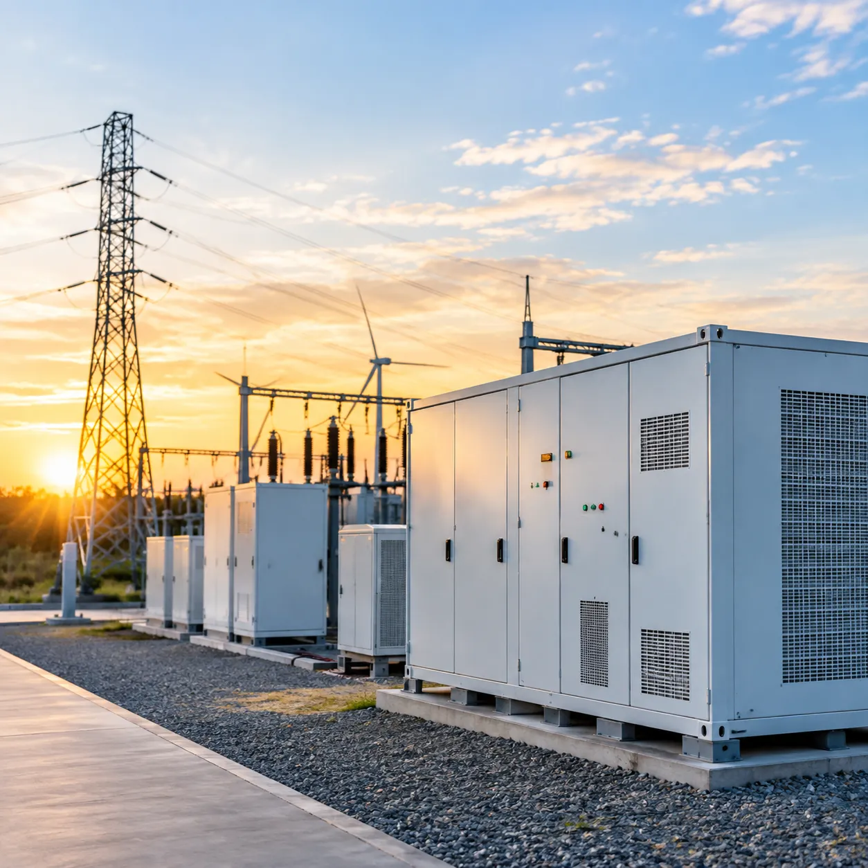
Evaluating the performance of battery energy storage system in weak grid conditions requires identifying how power electronics interact with high line impedance. When grid stiffness drops, small-signal dynamics can quickly trigger unwanted harmonic resonances and power fluctuations.
Weak Grid Impedance (High L/R) <---> Inverter Control Loops (PLL, Current)
│
┌─────────────┴─────────────┐
▼ ▼
Phase Lag & Cross-Coupling Harmonic Resonance
│ │
└─────────────┬─────────────┘
▼
Subsynchronous Oscillation (SSO)
[Trip Risk & Asset Stress]
Root Causes of Small-Signal Instability and Harmonic Resonances
Weak interconnects amplify control-loop interactions across wide frequency bands. Small disturbances that a stiff grid would absorb can cascade into persistent oscillations in high-impedance networks.
- Modal Coupling: Fast inverter inner-current loops interact with weak line reactance, shifting poles into unstable right-half planes.
- Harmonic Resonance: Inverter output filter capacitors interact with line inductances, creating parallel resonance points below nominal fundamental frequency (subsynchronous range).
- Control Cross-Talk: Adjacent renewable assets and inverter banks introduce cross-talk, degrading system-wide damping ratios.
Interaction Between Phase-Locked Loops (PLL) and High Grid Impedance
Grid-following converters rely on a Phase-Locked Loop (PLL) to track the voltage vector at the Point of Common Coupling (PCC). In weak grids with low short circuit ratios, this setup creates a severe vulnerability:
- Voltage-Angle Feedback Loop: Injected currents flow through high grid impedance, immediately shifting the PCC voltage angle.
- Negative Damping Effect: The PLL attempts to track this self-induced voltage shift, introducing phase lag and negative damping into the system.
- Control Degradation: High PLL gains cause active-reactive power cross-coupling, leading to phase angle jumps, loss of synchronization, and sudden inverter tripping.
Damping Control Strategies to Suppress Power and Voltage Oscillations
Mitigating subsynchronous oscillation (SSO) requires structured damping controls embedded directly within the converter firmware:
| Damping Method | Implementation Target | Primary Benefit |
|---|---|---|
| Virtual Impedance Damping | Current control loop | Reshapes output impedance to eliminate negative resistance at resonance bands |
| Active Damping Filters | Feedforward voltage path | Suppresses high-frequency filter interactions without physical resistor losses |
| Power Oscillation Damping (POD) | Outer power control loop | Injects counter-phase active/reactive power components to cancel SSO modes |
| Band-Pass Filtering | PLL tracking loop | Isolates fundamental frequency tracking from subsynchronous noise |
Utilizing a modular battery energy storage system for scalable power allows operators to segment inverter control nodes, applying targeted damping parameters across separate power conversion blocks to isolate oscillation risks.
Real-Time Impedance Monitoring and Adaptive Tuning Methods
Fixed control parameters cannot maintain stability across dynamic weak grid operating states. Adaptive control architectures solve this by continually adjusting to fluctuating line conditions:
- Online Grid Impedance Identification: The converter injects small, non-disruptive broadband perturbation signals to calculate real-time grid impedance and Short Circuit Ratio (SCR) at the PCC.
- Gain-Scheduling Controllers: Inverter control loops automatically adjust PLL bandwidth and proportional-integral (PI) gains as grid stiffness changes.
- Automated Mode Switching: When grid impedance exceeds critical stability thresholds, the control architecture dampens inner-loop response speeds or transitions dynamically toward voltage-source behavior, preventing unforced trips and preserving asset longevity.
Real-World Strategies to Optimize BESS Performance in Weak Grids
Advanced Inverter Tuning and Parameter Co-Optimization
Standard control loops often struggle when grid impedance shifts. Optimizing system performance across low-SCR connection points requires active parameter tuning:
Adaptive Control Gains: Automatically adjusting proportional-integral (PI) parameters based on real-time voltage sensitivity and Short Circuit Ratio (SCR) tracking.
Virtual Synchronous Generator (VSG) Damping: Fine-tuning virtual inertia and damping coefficients to suppress power oscillations and prevent phase-lock hunting.
Dynamic Reactive Power Prioritization: Reprogramming inverter firmware to prioritize fast voltage support over active power during severe transient voltage sags.
Hybrid Installations: Pairing BESS with Synchronous Condensers
When a remote grid node lacks physical inertia and short-circuit capacity, pairing a BESS with a synchronous condenser creates a balanced, high-strength solution:
| Grid Support Metric | Standalone BESS | Synchronous Condenser | Hybrid BESS + SynCon |
|---|---|---|---|
| Physical Inertia | Low (Emulated only) | High (True rotational) | High (Rotational + Synthetic) |
| Short-Circuit Current | Limited (1.1–1.2x rated) | High (Up to 8x rated) | High (Fault clearance capable) |
| Sustained Energy Dispatch | High (Hours of duration) | Zero | High (Full capacity dispatch) |
| Response Speed | Ultra-Fast (<20 ms) | Instantaneous electromechanical | Instantaneous + Continuous |
This hybrid setup relieves thermal stress on power conversion systems and allows utility-scale turnkey storage systems to operate reliably in extreme sub-1.5 SCR environments.
State-of-Charge (SoC) Management During Prolonged Frequency Events
Weak grids experience wider, more persistent frequency excursions that can rapidly deplete battery headroom. Robust operational strategies include:
Dynamic Deadband Scheduling: Modulating frequency deadbands dynamically to prevent unnecessary battery cycling during minor baseline drift.
Variable Droop Slopes: Adjusting droop response curves progressively as the battery SoC approaches operational thresholds (e.g., below 15% or above 85%).
Autonomous State Recovery: Scheduling rapid micro-charges and discharges during stable grid windows to keep the system primed for synthetic inertia duty.
Hardware-in-the-Loop (HIL) Simulation and Grid Compliance Testing
To avoid costly grid-connection delays, site-specific validation must occur in the lab before field commissioning:
Real-Time Digital Simulators (RTDS): Connecting actual inverter control hardware to high-fidelity electromagnetic transient (EMT) network models.
Fault Ride-Through Stress Testing: Simulating asymmetrical faults, weak-grid phase angle jumps, and subsynchronous resonance conditions.
Specification Validation: Verifying that standard battery energy storage container specifications meet localized grid code requirements under dynamic, weak-connection stresses.
Economic and Reliability Impact of Deploying BESS in Weak Grids
Deploying storage in weak, high-impedance networks is not just about keeping the power on—it is a critical financial lever. When we evaluate the performance of battery energy storage system in weak grid environments, the economic return hinges on how effectively the system prevents stability-related trips while unlocking premium grid service revenues.
CAPEX vs. OPEX Tradeoffs for Advanced Grid-Forming Systems
Upgrading to advanced grid-forming inverters and specialized control hardware slightly raises initial capital expenditure (CAPEX), but it drastically cuts lifecycle operational costs (OPEX).
- Initial Investment: Grid-forming inverters, larger DC-bus reserves, and real-time impedance monitoring require a 5% to 15% hardware and commissioning premium over standard grid-following setups.
- Operational Savings: Standard systems in low-SCR areas suffer from frequent nuisance tripping, curtailment fines, and expensive post-commissioning retrofits. Investing in a properly engineered scalable battery energy storage system for utilities eliminates recurring tuning costs and field patch downtime.
| Metric | Standard Grid-Following (GFL) BESS | Advanced Grid-Forming (GFM) BESS |
|---|---|---|
| Upfront Control & Hardware Cost | Baseline | +5% to 15% |
| Weak Grid Fault Ride-Through | Moderate to High Trip Risk | Robust Autonomous Stability |
| Unplanned Outage & Curtailment Risk | High in Low-SCR Networks | Minimal |
| Long-Term Grid Compliance OPEX | High (Requires Retuning) | Low (Self-Stabilizing) |
Revenue Streams Through Ancillary Services and Grid Support
Weak grids create urgent reliability challenges for transmission system operators (TSOs), driving higher compensation for fast-acting assets. By stabilizing weak points in the network, our battery energy storage systems capture multiple high-margin revenue streams:
- Fast Frequency Response (FFR): Sub-second active power injection commands top-tier clearing prices compared to standard primary frequency reserves.
- Synthetic Inertia Markets: Emerging capacity and stability markets pay dedicated premiums to systems that provide instantaneous, inertia-like power response.
- Dynamic Reactive Power Support: Supplying continuous VAR support locally reduces transmission voltage collapse risks, generating stable capacity payments without deeply cycling battery cells.
Minimizing Renewable Curtailment and Thermal Reliance
In weak grid corridors, system operators routinely curtail utility-scale solar and wind plants to avoid tripping local circuits. Deploying a high-performance BESS directly resolves this operational bottleneck:
- Unlocking Stranded Capacity: Strengthening the local short circuit ratio (SCR) enables nearby renewable assets to operate at rated output without triggering voltage oscillation limits.
- Displacing Must-Run Thermal Turbines: Traditional grids run expensive, carbon-heavy synchronous generators solely for physical inertia. Fast-response BESS replaces these units, reducing fossil fuel dependence and wholesale system balancing costs.
Asset Lifespan Protection and Battery Degradation Management
Aggressive weak grid support requires careful battery management to prevent accelerated cell wear. Maintaining high availability and asset health demands deliberate operational boundaries:
- Smart SoC Reserve Allocation: We dynamic-partition State-of-Charge (SoC), reserving a dedicated 10% to 15% capacity band strictly for transient frequency and inertia support, while utilizing the rest for standard energy arbitrage.
- Micro-Cycling Mitigation: Advanced inverter filtering stops high-frequency grid noise and voltage ripple from translating into continuous, micro-cycling battery throughput.
- Thermal Stress Reduction: Regulating short, peak current discharges during fault ride-through events prevents localized hot spots within the battery modules, protecting factory warranties and extending calendar life.
Frequently Asked Questions About BESS Performance in Weak Grids
Evaluating the performance of battery energy storage system in weak grid environments raises practical engineering questions around hardware limits, inverter controls, and system stability. Here are the direct answers to the most common technical questions we encounter.
What is the minimum Short Circuit Ratio (SCR) for a standard BESS?
A standard BESS operating with conventional grid-following (GFL) inverters typically requires a minimum Short Circuit Ratio (SCR) of 2.0 to 3.0 at the Point of Interconnection (POI) to maintain stable phase tracking.
- SCR > 3.0 (Strong Grid): Standard GFL inverters operate with stable phase-locked loop (PLL) tracking and dynamic reactive power support.
- SCR between 1.5 and 2.0 (Weak Grid): GFL inverters experience phase angle jumps, control interactions, and potential small-signal instability without custom retuning.
- SCR < 1.5 (Very Weak to Islanded Grid): Standard systems fail. Stable operation requires grid-forming inverter (GFMI) topologies or advanced custom ESS integration engineered for low-inertia networks.
How does a BESS provide synthetic inertia compared to a synchronous condenser?
Both assets deliver weak grid inertia support, but their underlying mechanics and response speeds differ:
- Synchronous Condensers: Provide true physical inertia instantly via rotating kinetic mass. They deliver massive short-circuit current during faults, but they cannot supply sustained active energy.
- BESS with Synthetic Inertia: Uses virtual synchronous generator (VSG) algorithms to emulate physical inertia electronically. A BESS provides fast frequency response (FFR) within milliseconds, dampens subsynchronous oscillations, and sustains active power injection for minutes or hours depending on capacity.
When evaluating utility-scale battery storage providers, pairing battery storage with synchronous condensers provides both immediate physical fault current and long-duration dynamic power balancing.
Can software updates convert a grid-following BESS to grid-forming?
In many modern systems, yes, but only if the underlying power hardware supports it. Converting a GFL unit to a grid-forming inverter requires:
- Inverter Firmware Compatibility: Replacing PLL-driven control loops with voltage source converter (VSC) algorithms, such as droop control or virtual synchronous machine controls.
- Current Overload Margin: Grid-forming units must absorb instantaneous power surges during line faults. If the power conversion system (PCS) lacks thermal and current headroom (typically 1.2x to 1.5x nominal rating), hardware upgrades are necessary.
- Filter and DC-Bus Capacity: Output LCL filters and DC-link capacitance must handle rapid voltage-source adjustments without triggering overvoltage protection.
What are the main causes of BESS tripping during weak grid faults?
Unplanned tripping during weak grid disturbances usually traces back to control-loop limitations rather than battery cell failures:
- Phase-Locked Loop (PLL) Instability: Severe phase angle jumps cause PLL loss of synchronism, forcing the inverter offline to protect its IGBT modules.
- AC Overcurrent and Voltage Spikes: High grid impedance causes sharp voltage swings during fault inception and clearing, breaching inverter threshold limits.
- Subsynchronous Resonance (SSR): Un-damped interactions between converter fast-inner controls and weak transmission lines trigger voltage oscillations.
- Strict Protective Relay Settings: Standard ride-through envelopes (such as frequency and voltage ride-through limits) trip prematurely if not tailored specifically for low-SCR interconnects.