Formula details
Product Details
Overview
What is a Liquid Cooled Energy Storage Cabinet?
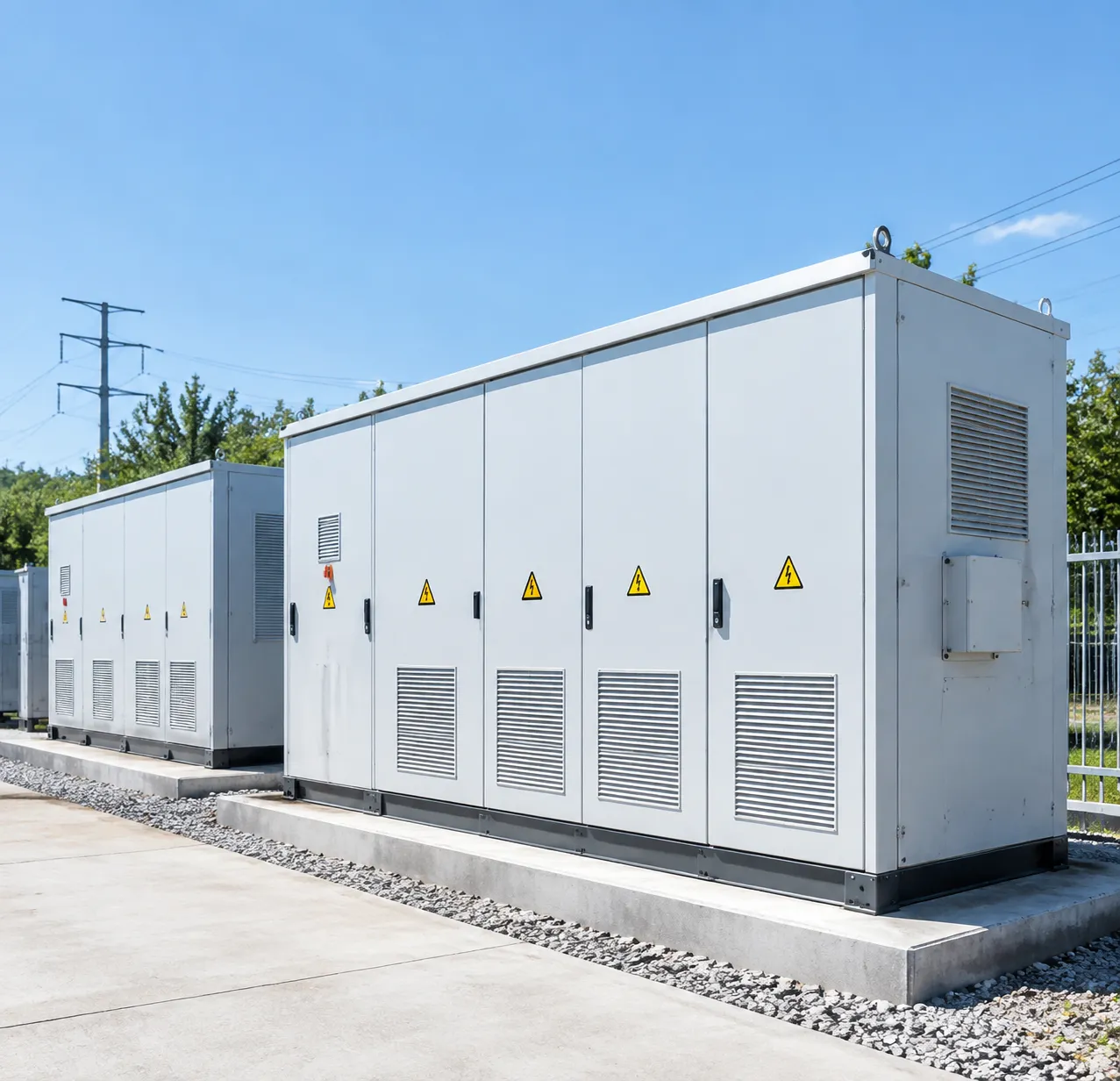
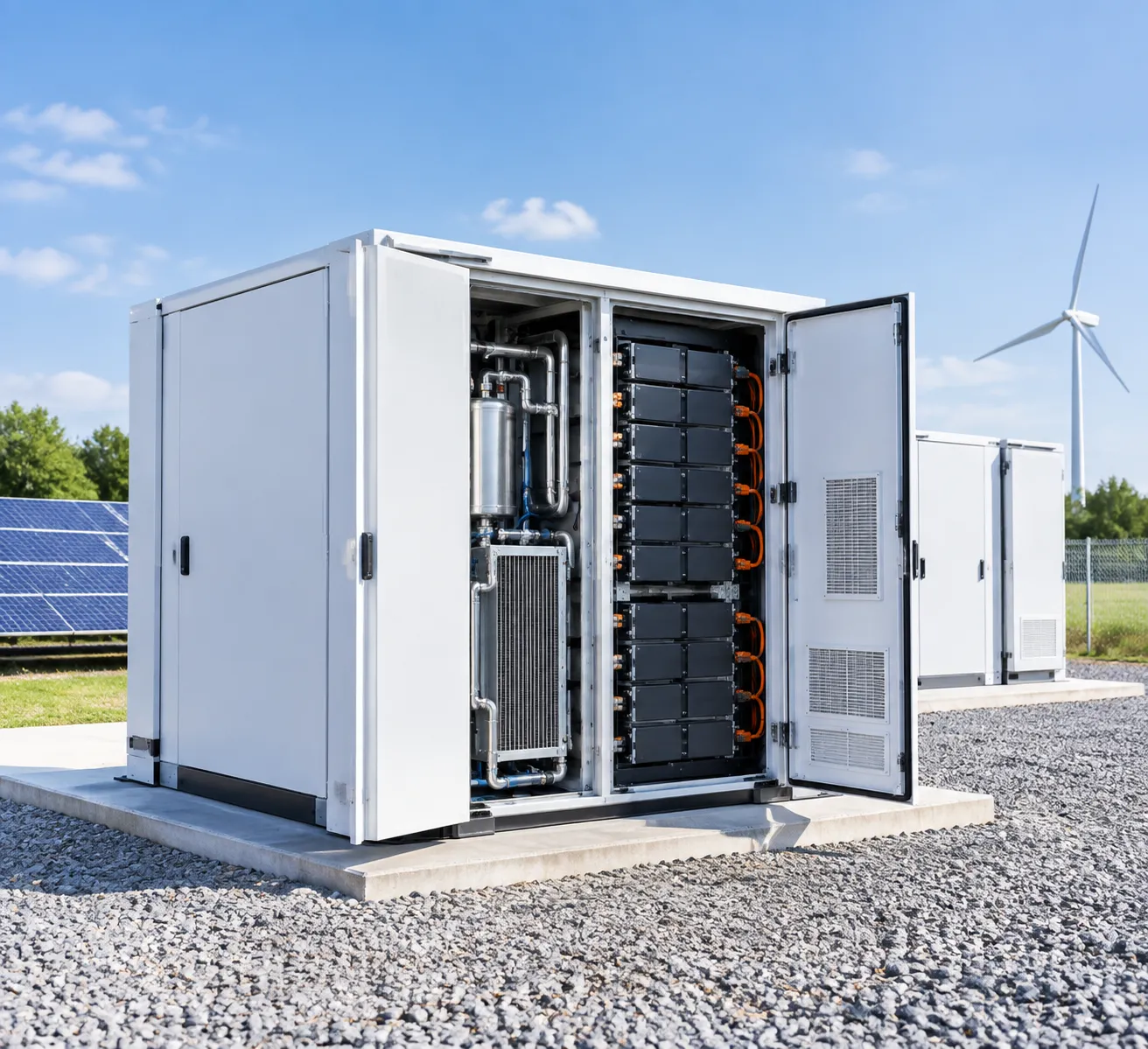
A liquid cooled energy storage cabinet is a factory-integrated, outdoor-rated battery enclosure engineered for commercial and industrial (C&I) applications. Instead of relying on traditional forced-air fans, our systems circulate a specialized liquid coolant through high-conductivity cold plates nestled directly against the battery cells.
This architecture delivers rapid heat dissipation, precise temperature balancing, and an ultra-compact physical footprint.
Core Working Principles of Liquid-Cooled Battery Cabinets
Our liquid cooled BESS manages internal temperatures dynamically through closed-loop conduction:
- Direct Thermal Conduction: Cold plates make physical contact with LiFePO4 cell surfaces, extracting heat 3 times faster than ambient air flow.
- Closed-Loop Fluid Dynamics: A low-conductivity water-glycol mixture flows continuously through the internal channels, absorbing thermal energy during charge and discharge cycles.
- Dynamic Chiller/Heater Regulation: An integrated thermal unit automatically switches between active refrigeration, passive heat dissipation, and positive temperature coefficient (PTC) heating based on real-time cell telemetry.
How the Battery Thermal Management System (BTMS) Functions
[ Battery Cells ] <---> [ Cold Plates ] <---> [ Coolant Loop ] <---> [ Integrated Chiller / Heat Exchanger ]
The BTMS maintains the entire pack within an optimal operating window of 15°C to 35°C, keeping cell-to-cell temperature variance Delta T ≤ 2.5°C.
- Cell Telemetry: Multi-point temperature sensors feed real-time thermal profiles to the internal Battery Management System (BMS).
- Variable Flow Control: The BMS adjusts the variable-speed pump and coolant distribution unit (CDU) to match load conditions.
- Dual-Mode Response: Under heavy C-rate cycling, the compressor activates for rapid chilling; in sub-zero ambient conditions, the internal heater warms the coolant to protect cell chemistry from lithium plating.
All-in-One Outdoor ESS Cabinets vs. Containerized Solutions
| Feature | All-in-One Liquid Cooled Cabinet | Containerized BESS (20ft/40ft) |
|---|---|---|
| Typical Capacity | 100kWh – 400kWh per unit | 1MWh – 5MWh+ |
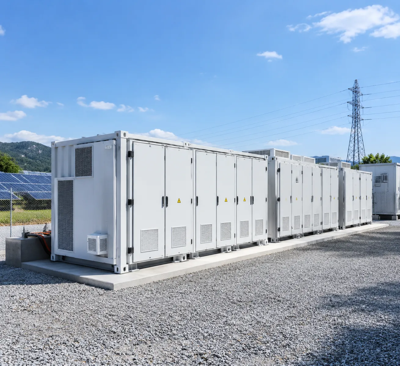
| Footprint Flexibility | Modular, decentralized, fits tight C&I spaces | Requires large civil pads and crane access |
| Installation Time | Plug-and-play (under 1-2 days) | Multi-week commissioning cycle |
| Thermal Efficiency | Direct cold-plate liquid contact | Often mixed (Air/Liquid hybrid) |
| Target Application | EV charging stations, factories, microgrids | Utility-scale front-of-the-meter generation |
| Expansion Capability | Direct parallel modular stacking | Fixed multi-megawatt blocks |
Core Components of a Liquid Cooled ESS Cabinet
High-Density Lithium Iron Phosphate (LiFePO4) Battery Packs
The core energy block relies on grade-A LFP cells assembled into high-voltage strings. LiFePO4 chemistry provides inherent chemical stability, deep cycle life, and low degradation rates under continuous heavy cycling. Using a dedicated commercial lithium battery energy storage system with BMS, our pack designs achieve high volumetric energy density while keeping every cell physically secured against vibration and thermal expansion.
Liquid Cooling Distribution Unit (CDU) and Cold Plates
Direct-contact aluminum cold plates sit flush against the base and sides of the battery modules.
- Micro-channel cold plates: Maximize the surface contact area with each cell to pull heat away directly at the source.
- Coolant Distribution Unit (CDU): Balances fluid pressure and flow rates across every parallel branch, ensuring uniform temperature across the entire rack.
- Quick-connect dry-break couplings: Eliminate fluid leakage risks during factory assembly and routine field servicing.
Integrated Battery Management System (BMS) and Energy Management System (EMS)
Precision control requires multi-tier monitoring:
- Pack-level BMS: Reads individual cell voltages, state of charge (SOC), state of health (SOH), and multi-point temperature sensors in real time.
- System-level EMS: Coordinates dispatch strategies, schedules peak shaving routines, and actively throttles chiller output based on current power demand and ambient weather forecasts.
Circulation Pump, Heat Exchanger, and Industrial Chiller Modules
The hydraulic loop uses an integrated industrial chiller module paired with a variable-speed circulation pump and plate heat exchanger. When temperatures rise during high C-rate charging, the compressor cycles on to cool the closed-loop water-glycol mixture. In colder seasons, integrated PTC heaters warm the coolant to bring cold cells to ideal operating temperatures before charging begins. Engineered directly at our battery energy storage system factory in China (LiFePO4 BESS), this thermal setup slashes parasitic power loads and keeps cell-to-cell temperature variation strictly within 2°C to 3°C.
Liquid Cooling vs. Air Cooling: Performance and Efficiency Comparison
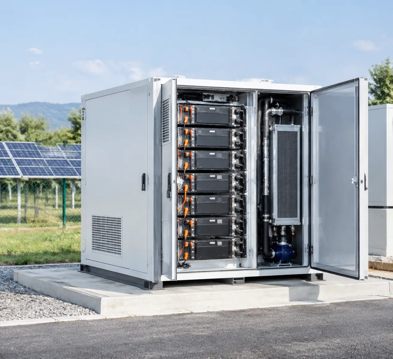
When choosing the right thermal architecture, comparing liquid cooling and forced-air cooling directly highlights why the industry is shifting toward liquid systems:
| Metric | Liquid Cooled ESS Cabinet | Standard Air-Cooled Cabinet |
|---|---|---|
| Cell Temperature Delta (ΔT) | ≤ 2.5°C across all cells | 5°C to 8°C variations |
| Auxiliary Power Consumption | 20% to 30% lower parasitic load | High continuous fan draw |
| Volumetric Energy Density | Up to 40% higher per footprint | Low due to required airflow gaps |
| Operating Noise Level | < 65 dB(A) at full load | 75 to 85 dB(A) high-speed blowers |
| Cycle Life Retention | Extended by 20–25% | Faster degradation from hotspots |
Precise Temperature Uniformity
Air cooling struggles to distribute heat evenly across high-density battery racks, frequently leading to localized hotspots. Our liquid cooling distribution plates run directly beneath the cells, keeping the core temperature variation within ΔT ≤ 2–3°C. This balanced thermal profile prevents uneven cell aging, ensuring that every cell within the pack degrades at the same predictable rate.
Drastic Parasitic Load Reduction
Air cooling relies on high-power fans running continuously to move thousands of cubic feet of air. Liquid carries heat roughly 3,000 times more efficiently by volume than air. By moving coolant with a low-power variable-speed pump, our systems cut auxiliary HVAC power consumption significantly, delivering higher overall round-trip efficiency (RTE) back to your facility.
Higher Energy Density and Smaller Footprint
Air cooling requires wide air channels between battery modules to ensure sufficient ventilation, which wastes valuable site area. Because liquid cold plates contact the cells directly, we eliminate bulky air ducts. This lets us pack significantly more capacity—such as standard 215kWh or 260kWh modular blocks—into a much smaller physical enclosure. You can explore how these spatial and layout advantages fit broader site plans in our energy storage system architecture and design guide.
Noise Suppression and High C-Rate Resilience
Fast-charging and peak-demand discharge cycles (0.5C to 1C) generate rapid heat spikes. Under these demanding conditions, air systems spin up loud industrial fans that create severe noise pollution in commercial zones. A liquid cooled energy storage cabinet handles intense thermal surges quietly, protecting cell chemistry from high-temperature degradation while maintaining quiet, neighborhood-friendly operation.
Key Advantages of Liquid Cooled Battery Cabinets
Enhanced Fire Safety and Thermal Runaway Mitigation
Safety starts at the cell level. Our liquid cooling architecture places dedicated cold plates directly against each battery module, pulling heat away before local hot spots form.
- Active Heat Dissipation: Rapidly removes heat during high charge and discharge cycles, preventing thermal propagation across neighboring cells.
- Thermal Runaway Mitigation: By keeping cell-to-cell temperature variations tight, the risk of dendrite formation and localized short circuits drops dramatically.
- Safer Chemistry Integration: Combined with inherently stable cells, this design enhances the overall LFP battery energy storage safety, cost, and lifespan profiles across multi-megawatt deployments.
Stable Performance in Extreme Ambient Temperatures (-30°C to 50°C)
Ambient weather extremes severely degrade unmanaged batteries. Our liquid cooling systems integrate dual-mode heating and chilling loops that adapt automatically to external conditions.
| Operating Condition | Thermal System Action | Operating Result |
|---|---|---|
| Extreme Heat (up to 50°C) | High-efficiency chiller circulates chilled coolant | Caps internal cell temps below 35°C under heavy loads |
| Freezing Cold (down to -30°C) | Internal PTC heating elements warm the coolant | Preheats battery cells before charging to prevent lithium plating |
This bidirectional control allows every liquid cooled ESS cabinet to deliver full power output without derating, whether deployed in desert solar farms or sub-zero northern regions.
High IP Ratings (IP55/IP65) for Harsh Outdoor Environments
Traditional air-cooled units pull huge volumes of outside air through the cabinet, dragging in dust, moisture, and corrosive salt air. A sealed liquid cooled setup changes the equation entirely:
- Fully Enclosed Design: The battery compartment uses an isolated internal loop, enabling robust IP55 or IP65 ingress protection.
- Environmental Resistance: Dust, sand, coastal salt spray, and industrial pollutants cannot reach sensitive high-voltage connections or cell terminals.
- Flexible Siting: Deploy this rugged outdoor battery energy storage system with LiFePO4 battery packs directly on unpaved gravel pads, industrial docks, or desert substations without requiring cleanrooms or secondary housing.
Lower Levelized Cost of Storage (LCOS) and Extended Cycle Life
Thermal stress is the primary driver of battery cell degradation. By maintaining uniform temperatures across all battery packs, a liquid cooled BESS protects your capital investment over decades:
- Cycle Life Extension: Keeping cell temperature differentials within 2°C to 3°C extends battery lifespan by up to 20% compared to air-cooled alternatives, achieving 6,000 to 8,000+ continuous cycles.
- Reduced Parasitic Load: Liquid coolant carries significantly more heat per unit volume than air, slashing thermal auxiliary energy consumption by up to 30%.
- Lower LCOS: Fewer cell replacements, lower auxiliary power bills, and minimal routine maintenance translate directly into higher project ROI and the lowest possible Levelized Cost of Storage over the asset lifecycle.
Primary Applications and Use Cases
A liquid cooled energy storage cabinet adapts seamlessly across diverse operational settings where high power density, thermal safety, and footprint savings matter most. Here is how we deploy these systems across key sectors:
Commercial and Industrial (C&I) Peak Shaving and Demand Management
Utility demand charges can represent up to 50% of a commercial electric bill. We use our commercial & industrial energy storage systems to cap facility peak loads automatically:
Demand Charge Reduction: The liquid cooled BESS discharges instantly during peak operating hours to flatten spikes in energy draw, delivering clear financial benefits of peak shaving.
Time-of-Use (TOU) Arbitrage: The cabinet charges during low-cost, off-peak hours and discharges during expensive on-peak tariff windows.
Continuous High-Rate Discharge: Liquid cooling keeps cell temperatures stable during sustained high C-rate discharge cycles without thermal throttling.
Solar-Plus-Storage and Microgrid Integration
Renewable generation is inherently intermittent. Integrating a liquid cooled battery storage unit stabilizes clean energy assets:
Solar Self-Consumption: Storing excess mid-day photovoltaic generation for evening use maximizes onsite solar ROI.
Islanded Microgrids: In remote or weak-grid environments, our cabinets act as voltage and frequency anchors, ensuring smooth power transfer during grid dropouts.
Ramp-Rate Control: Absorbs sudden fluctuations caused by passing clouds or sudden load changes, protecting local electrical infrastructure.
EV Ultra-Fast Charging Station Power Buffering
High-power DC fast chargers (150kW–350kW+) put severe stress on local distribution grids.
Grid Capacity Extension: The energy storage cabinet acts as a local energy reservoir, delivering high burst currents to fast chargers without requiring costly utility transformer upgrades.
Continuous High-C Cycling: Liquid cooling handles the rapid, back-to-back charge and discharge cycles common at busy fleet depots and highway charging hubs.
Emergency Backup Power and Grid Frequency Regulation
Grid instability requires millisecond-level response times that conventional mechanical generators cannot match:
Critical Backup (UPS-Grade): Supplies clean, uninterrupted power to hospitals, data centers, and manufacturing plants during utility blackouts.
Ancillary Services: Supports fast frequency response (FFR) and voltage regulation programs, unlocking additional grid service revenue streams for asset owners.
| Application Sector | Key System Role | Primary Operational Benefit |
|---|---|---|
| C&I Facilities | Peak shaving & TOU shifting | Direct utility bill savings & lower demand penalties |
| Microgrids & Solar | Smoothing & islanding support | Maximum renewable uptime & stable microgrid power |
| EV Charging Hubs | High-power load buffering | Lower grid interconnection costs & avoided peak tariffs |
| Grid Ancillary | Fast frequency response (FFR) | Grid compliance & secondary revenue generation |
Safety Architecture and Fire Protection in Liquid Cooled Energy Storage Cabinets
Multi-Level Early Warning and Gas Detection
Preventing cell degradation requires detecting venting products minutes before smoke or open flames appear:
Off-Gas Monitoring: Advanced electrochemical sensors track trace hydrogen ($H_2$), carbon monoxide ($CO$), and volatile organic compounds ($VOC$) at the pack level. Integrating certified battery storage fire detection systems with off-gas sensors provides critical response time before temperatures spike.
Continuous Parameter Sampling: The internal BMS tracks cell voltages, rapid voltage drops, and localized temperature variations ($Delta T$) across all cooling channels in real time.
Automated Clean-Agent Fire Suppression
When a thermal threshold is crossed, the liquid cooled BESS deploys automatic, localized fire extinguishing agents:
Pack-Level Targeted Injection: Direct nozzle lines discharge Novec 1230 (FK-5-1-12) or condensed aerosol agents straight into the affected battery pack module.
Cabinet Total Flooding: Secondary clean-agent discharge blankets the internal enclosure, starving the environment of oxygen without leaving corrosive residues on high-voltage connections.
| Protection Feature | Mechanism | Primary Function |
|---|---|---|
| Off-Gas Detection | H₂, CO, and smoke sensors | Triggers pre-alarm and emergency circuit trip |
| Clean Agent Suppression | Novec 1230 / aerosol canisters | Rapid flame extinguishing and localized cooling |
| Leak Detection Trays | Optical / conductivity sensors | Isolates cooling loops upon glycol detection |
| Deflagration Venting | Directional explosion-relief panels | Releases internal overpressure safely upward |
Coolant Leak Detection and Electrical Isolation
Liquid cooling loops require fail-safe fluid control to protect high-voltage electrical circuits:
Optical and Resistive Leak Sensors: Positioned beneath each cold plate and inside the lower drip tray to catch drops instantly.
Automated Loop Shut-Off: Solenoid valves isolate leaking cooling segments within milliseconds, preventing fluid spread across the pack.
High-Voltage Interlock Loop (HVIL): Instantly opens the main DC contactors to de-energize the cabinet if coolant moisture or ground-fault leakage is detected.
Deflagration Venting and Pressure Relief
To eliminate explosive pressure buildup inside sealed outdoor battery energy storage systems:
NFPA 68/69 Compliant Panels: Top-mounted deflagration vents release high-pressure gases upward and away from service personnel.
Pack-Level Vent Valves: Bi-directional pressure valves on individual cell packs balance internal barometric changes while exhausting battery off-gases directly toward the exhaust duct.
How to Choose the Right Liquid Cooled Energy Storage Cabinet
Selecting the ideal liquid cooled energy storage cabinet comes down to balancing energy capacity, discharge speed, compliance, and long-term operating costs. We design our systems to take the guesswork out of deployment, ensuring your facility gets exact power delivery without overspending on unneeded hardware.
1. Determining Capacity and Power Ratings
Match your cabinet sizing directly to your facility load profile and utility rate structure:
100kW / 215kWh systems: The industry standard for commercial demand charge management and standard peak shaving.
125kW / 260kWh systems: Ideal for facilities requiring extended 2-hour backup durations and higher energy density per square foot.
For scalable deployments, our modular energy storage cabinets allow parallel connections to scale from hundreds of kilowatt-hours up to multi-megawatt configurations seamlessly.
2. Evaluating C-Rate Capabilities
Your operational use case dictates whether you need a 0.5C or 1C liquid cooling system:
0.5C Systems (2-Hour Discharge): Best for solar self-consumption, energy time-shifting, and routine peak shaving.
1C Systems (1-Hour Discharge): Necessary for EV fast-charging buffers, dynamic frequency response, and critical industrial emergency backup where high burst power is essential.
Key Selection Criteria Comparison
| Feature | 0.5C Liquid Cooled ESS | 1C Liquid Cooled ESS | Key Evaluation Factor |
|---|---|---|---|
| Typical Rating | 100kW / 215kWh | 125kW / 125-260kWh | Match to peak load demand |
| Target Application | Peak shaving, microgrids | EV charging buffer, grid support | Power-to-energy ratio |
| Thermal Load | Moderate | High (requires high-flow CDU) | Coolant flow rate & chiller capacity |
| Target Cycle Life | 6,000 to 8,000+ cycles | 5,000 to 7,000+ cycles | Cell temperature delta (maintain under 3°C) |
3. Safety Certifications and Compliance
Never compromise on bankability and safety standards. Ensure the equipment carries:
UL 9540 & UL 9540A: Validates system-level safety and certifies zero thermal runaway propagation.
NFPA 855: Ensures compliance with standard installation spacing and fire protection codes.
IEC 62619 & UN 38.3: Verifies core LiFePO4 battery pack integrity and transport safety.
4. Coolant Maintenance, Warranty, and Vendor Support
Look for closed-loop thermal designs that minimize field upkeep. We prioritize pre-mixed ethylene glycol solutions with 5-year replacement intervals, tool-less quick-disconnect couplings on battery racks, and 10-year comprehensive performance warranties backed by 24/7 cloud monitoring.
Installation, Commissioning, and Maintenance Guidelines for Liquid Cooled Energy Storage Cabinets
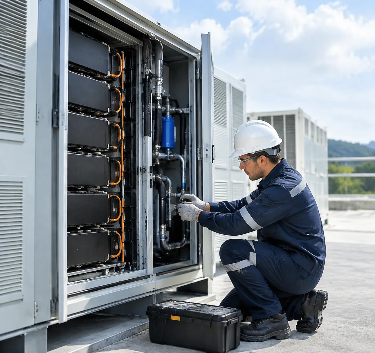
Deploying an outdoor liquid cooled energy storage cabinet requires a streamlined installation process, strict hydraulic commissioning, and routine preventative care. We engineer our systems for rapid field setup, but following core mechanical and thermal protocols ensures maximum uptime and system longevity.
Civil Foundation and Clearance Requirements
A stable, level concrete pad is essential to handle the high volumetric energy density and mechanical weight of a fully populated liquid cooled ESS cabinet.
- Foundation Pad: Reinforced concrete base rated for dynamic and static loads (minimum 2,500–3,000 kg depending on system capacity), with a levelness tolerance within ±2 mm.
- Service Clearances: Maintain at least 1,000 mm (3.3 ft) in the front and rear for door swing and module replacement, plus 800 mm on chiller exhaust sides to ensure unhindered airflow.
- Cable and Pipe Entry: Bottom entry conduits for AC/DC power, communication lines, and auxiliary power feeds with IP65-rated sealing glands.
| Requirement | Specification | Purpose |
|---|---|---|
| Pad Thickness | 150 mm to 200 mm reinforced concrete | Structural stability and vibration damping |
| Front/Rear Clearance | Minimum 1,000 mm | Safe technician access and module extraction |
| Side Clearance | Minimum 800 mm | Chiller heat rejection and ventilation |
| Drainage Slope | 1% grade away from the cabinet | Prevents water pooling around the base |
Coolant Loop Filling, Pressure Testing, and Glycol Mix Ratios
Proper commissioning of the liquid cooling distribution unit (CDU) and cold plate circuits guarantees leak-free operation and optimal heat transfer across every LiFePO4 battery pack.
1. Pneumatic Hold Test (Hold 0.4–0.6 MPa for 30 mins to verify zero pressure drop)
↓
2. Vacuum Purging (Evacuate air pockets from cold plates and manifolds)
↓
3. Coolant Injection (Pre-mixed inhibited ethylene or propylene glycol solution)
↓
4. Hydraulic Circulation (Run pumps at low speed to bleed remaining micro-bubbles)
- Coolant Fluid: We use a 50/50 mix of inhibited ethylene glycol and deionized water for sub-zero freeze protection down to -35°C (-31°F) and corrosion inhibition. Propylene glycol blends are used where local environmental codes mandate non-toxic solutions.
- Pressure Testing: Every loop undergoes a dual-stage test—a dry nitrogen hold followed by a wet hydraulic pressure hold at 1.5 times the normal working pressure before electrical power-up.
Routine Maintenance Checklist
Our liquid-cooled architecture significantly cuts down mechanical maintenance compared to high-flow air filters, but key subsystems require scheduled checks to sustain peak efficiency:
- Coolant Quality Check (Every 12 Months): Test pH levels (target: 7.5–9.5), refractive index for glycol concentration, and visual clarity to prevent scaling or fluid breakdown.
- CDU Filter Screen Cleaning (Every 6–12 Months): Inspect and clean the Y-strainer and in-line particulate filters to maintain stable flow rates.
- Pump and Valve Inspection (Every 12 Months): Check the circulation pump for bearing noise, vibration, and seal integrity. Verify electric proportional three-way valve actuation.
- BMS/Sensor Calibration (Every 12 Months): Calibrate module-level temperature sensors, liquid pressure transducers, and flow rate sensors to prevent false alarms. Our seamless BMS and EMS integration streamlines this by syncing local sensor calibration routines with higher-level plant controllers.
Remote Monitoring and Automated Diagnostics
Every liquid cooled BESS includes integrated industrial controllers that pipe telemetry straight to the cloud:
- Real-Time Pressure & Flow Tracking: Automated alerts trigger immediate pump adjustments if the loop detects unexpected pressure drops or rising flow resistance.
- Predictive Thermal Anomaly Detection: Cloud algorithms compare pack-to-pack temperature differentials. If any cell deviates beyond 3°C from the cluster average, the system flags the specific cold plate branch for inspection.
- Over-the-Air (OTA) Updates: Firmware updates for thermal management control curves, chiller logic, and BMS safety limits deploy remotely without on-site service calls.
Frequently Asked Questions About Liquid Cooled Energy Storage Cabinets
How often does the liquid coolant need to be replaced?
In our liquid cooled energy storage cabinet designs, the closed-loop thermal fluid (typically an inhibited ethylene or propylene glycol water solution) is built for extended operation.
Replacement Cycle: Every 3 to 5 years under standard duty cycles.
Routine Checks: An annual test of fluid pH, freeze point, and corrosion inhibitor levels keeps the loop in spec.
Sealed Reliability: Self-sealing quick-disconnect couplings minimize fluid loss, making routine top-ups rare during normal preventive maintenance.
Can liquid-cooled ESS cabinets operate safely in sub-zero climates?
Yes. Liquid-cooled systems excel in freezing temperatures down to -30°C (-22°F).
Anti-Freeze Formulations: Industrial glycol mixtures prevent line freezing even during prolonged grid outages.
Active Pre-Heating: Before accepting a charge in freezing conditions, the battery thermal management system (BTMS) engages integrated PTC electric heaters to circulate warm fluid through the cold plates, bringing cells up to safe operational temperatures and preventing lithium plating.
What happens if a coolant leak occurs inside the cabinet?
Our cabinets use multi-tier containment and detection architectures to eliminate electrical and physical risks:
Real-Time Detection: Point-level liquid sensors and pressure transducers line the coolant distribution unit (CDU) and pack trays.
Automated Isolation: The BMS immediately shuts off the circulation pump, isolates the affected cooling branch, and signals an alert if an unexpected pressure drop occurs.
Physical Segregation: Coolant manifolds are isolated from high-voltage DC busbars and battery terminals to avoid electrical bridging. For specific site requirements, we configure these safety layers via custom ESS integration.
How does liquid cooling impact the overall round-trip efficiency (RTE)?
Liquid cooling delivers a net positive impact on system efficiency, delivering 88% to 92% AC-AC round-trip efficiency (RTE):
| Efficiency Factor | Air-Cooled Systems | Liquid Cooled Cabinets |
|---|---|---|
| Auxiliary Power Draw | High (constant HVAC fan loads) | Up to 30–40% lower parasitic load |
| Cell Temperature Delta (ΔT) | 5°C to 8°C variations | Uniform ≤ 2°C to 3°C across all cells |
| Internal Resistance Losses | Higher due to thermal hotspots | Consistently low across all C-rates |
By maintaining uniform cell temperatures and minimizing HVAC runtime, liquid cooling preserves usable battery capacity and cuts operational overhead. For a detailed breakdown of performance benchmarks, refer to our BESS buying guide.