Formula details
Product Details
Overview
What Is a High Voltage Energy Storage Cabinet?
A high voltage energy storage cabinet is a self-contained, pre-engineered DC energy storage unit designed to operate at DC bus voltages typically ranging from 200V to over 1000V DC.
Definition and Core System Components
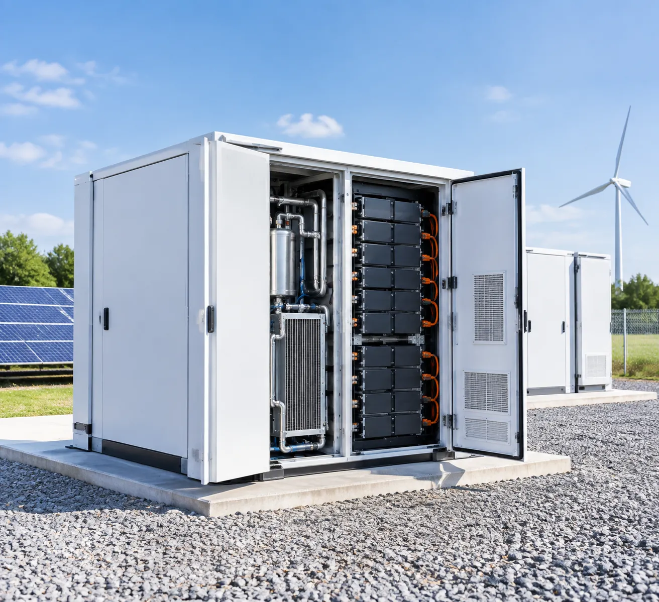
Our high voltage battery storage cabinet integrates electrochemical storage, multi-tier protection, and smart control into a unified, all-in-one footprint.
The core system architecture includes:
- High-Voltage Battery Modules: Series-connected Lithium Iron Phosphate (LiFePO4/LFP) cell packs configured to meet target bus voltage requirements.
- High-Voltage Control Box (BCU/BPU): Central DC switching unit equipped with high-voltage DC contactors, fast-acting fuses, pre-charge circuits, and isolation monitoring.
- Three-Tier Battery Management System (BMS): Microprocessor-driven monitoring hierarchy (Cell -> Module BMU -> Rack Master BMS) ensuring real-time telemetry over voltage, current, and cell temperatures.
- Power Distribution and Isolation: Built-in DC disconnect switches, circuit breakers, and surge protection devices (SPD).
- Active Thermal Management: Integrated industrial HVAC air conditioning or precision liquid cooling plates to maintain uniform core operating temperatures.
- Multi-Stage Safety and Fire Suppression: Automated aerosol or clean-agent fire extinguishing systems integrated with multi-criteria smoke, temperature, and off-gas detectors.
Working Principle and Energy Flow
The high voltage energy storage cabinet functions as a bidirectional DC energy buffer that communicates seamlessly with a Power Conversion System (PCS) or hybrid solar inverter:
- Charging Sequence (AC to DC / Solar to DC): Excess generation from the grid or an on-site photovoltaic (PV) array enters the PCS. The PCS rectifies AC to DC (or steps down high-voltage solar DC) and injects regulated current into the battery rack via the high-voltage DC junction box under active BMS closed-loop control.
- Holding and Standby: The master BMS continuously balances cell states, monitors insulation resistance, and keeps the pack within target thermal boundaries using onboard climate controls.
- Discharging Sequence (DC to AC): When facility demand peaks or a grid outage occurs, the cabinet delivers high-voltage DC power directly to the PCS. The PCS inverts the high-voltage DC into 3-phase AC power to supply facility loads or feed frequency regulation services to the grid.
Because the system operates at a high DC voltage matching typical inverter DC link levels, the current throughput remains low, maximizing round-trip efficiency (RTE).
Key Differences Between High-Voltage and Low-Voltage Systems
| Parameter | Low Voltage (LV) Systems (48V / 51.2V) | High Voltage (HV) Systems (200V – 1000V+) |
|---|---|---|
| Operating DC Voltage | Nominal 48V – 60V DC | Nominal 200V – 1000V+ DC |
| Current for Equivalent Power (100 kW) | ~2000 A (requires massive busbars) | ~125 A to 150 A (standard cabling) |
| I²R Thermal Energy Loss | High (current-driven heat dissipation) | Extremely Low (minimal heat generation) |
| Round-Trip Efficiency (RTE) | 85% – 89% | 91% – 96%+ |
| Cable Sizing and Installation Cost | Thick, heavy copper cables; complex paralleling | Thinner gauge wiring; lower balance of system (BOS) cost |
| PCS & Inverter Topology | Requires bulky, high-ratio DC-DC boost stage | Direct DC-bus coupling with commercial 3-phase PCS |
| Primary Target Applications | Residential, telecom backup, light commercial (<30 kWh) | C&I peak shaving, microgrids, EV fast-charging, utility scale |
High Voltage Energy Storage Cabinet System Architecture
We engineer our high voltage energy storage cabinet architecture to deliver an integrated, plug-and-play solution for commercial and industrial demands. By housing energy storage, battery management, power distribution, and thermal controls in a single unified footprint, we eliminate complex on-site assembly. For a broader overview of system configurations, reference our energy storage system architecture and design guide.
Modular Battery Packs and High-Voltage Rack Design
Our high voltage battery rack system uses series-connected, modular battery packs configured to reach operational DC voltages ranging from 500V to over 1000V.
- Modular Enclosure: Standardized plug-in sub-packs simplify capacity scaling and field maintenance.
- Busbar Interconnects: Heavy-duty, touch-safe copper busbars reduce internal resistance and eliminate wiring clutter.
- Vibration and Seismic Damping: Reinforced structural steel frames protect internal cell matrices against physical stress during transport and operation.
High-Voltage Energy Storage Cabinet Architecture
System Control Layer Master BMS & EMS Interface ↓ Power Distribution Layer High-Voltage Control Box & PDU ↓ Modular Battery Pack Assembly
Modular Pack N: Series-connected DC string
Modular Pack 2: BMU + thermal sensor matrix
Modular Pack 1: LiFePO₄ cells + balancing circuit
↓ Thermal & Safety Management Industrial HVAC / Liquid Cooling Plate
Integrated Battery Management System (BMS) Functionality
The multi-tiered BMS continuously tracks cell parameters to safeguard performance and maximize lithium iron phosphate battery system safety and cycle life.
- Module-Level BMU: Monitors real-time individual cell voltages, temperatures, and dynamic passive or active cell balancing.
- Rack-Level BCU/BMS: Aggregates module telemetry, calculates high-precision State of Charge (SOC) and State of Health (SOH), and governs string-level limits.
- System Isolation Management: Real-time insulation resistance monitoring isolates faults before they affect upstream infrastructure.
Power Distribution and Circuit Protection Components
Every modular energy storage cabinet contains an isolated High-Voltage Control Box (HVCB) that manages primary DC power routing and system protection:
- DC Contactors & Fuses: Fast-tripping, high-breaking-capacity DC fuses paired with positive and negative main contactors.
- Circuit Breakers & Disconnects: Manual lock-out/tag-out (LOTO) isolation switches for maintenance crews.
- Surge Protection Devices (SPD): Type II DC surge arresters protect control circuits and battery stacks against transient overvoltages.
- High-Voltage Interlock Loop (HVIL): Instantly triggers contactor open states if access panels, covers, or cable interconnects are compromised.
Thermal Management and HVAC Cooling Solutions
To maintain cell temperature uniformity within ±2°C to ±3°C, we apply dedicated thermal regulation depending on environmental constraints:
- Industrial HVAC Air Cooling: Top-mounted or door-mounted cycle units that direct conditioned airflow across individual packs to avoid hot spots.
- Liquid Cooling ESS Cabinet Architecture: Direct-to-pack liquid cooling plates circulating water-glycol mixtures, offering higher thermal efficiency and compact dimensions for high C-rate applications.
- Condensation Control: Internal heating strips and smart dehumidification prevent internal moisture buildup in outdoor installations.
EMS, PCS, and Inverter Communication Integration
The high voltage BESS cabinet seamlessly bridges DC battery banks with AC site infrastructure through open, standardized communication links.
| Subsystem Component | Primary Interface | Supported Protocol | Key Function |
|---|---|---|---|
| BMS to PCS (Inverter) | Dual CAN / RS485 | CAN 2.0B / Modbus RTU | Dynamic charge/discharge current limits, rack fault status |
| BMS to Site EMS | RJ45 Ethernet | Modbus TCP/IP | SOC/SOH reporting, alarms, telemetry, operational state |
| Fire Safety System | Dry Contacts / RS485 | Digital I/O | Emergency shutdown trigger, HVAC shut-off, venting activation |
| Cloud Telemetry Gate | 4G LTE / Ethernet | MQTT / HTTPS | Remote diagnostics, data logging, firmware OTA updates |
Core Features and Engineering Advantages
High Energy Density and Compact Footprint
Our high voltage architecture reduces system-level current, allowing us to use thinner conductors, minimize internal resistive heat losses, and maximize usable volumetric density.
- Space-Saving Design: Delivers up to 40% higher energy density compared to traditional low-voltage battery racks, drastically cutting down installation real-estate.
- Integrated Layout: Battery modules, high-voltage control boxes, BMS, and thermal subsystems are housed within a single compact battery energy storage system enclosure.
- Lower Balance of System (BOS) Costs: Smaller cable gauges and streamlined DC combiner configurations lower upfront hardware and labor expenses.
Modular Scalability for Multi-Cabinet Expansion
Scalability is central to our engineering approach. Whether you are scaling up for microgrid peak shaving or configuring dedicated commercial and industrial backup power systems, our modular design adapts directly to your load requirements.
- Plug-and-Play Paralleling: Connect multiple cabinets on a common DC bus or via multi-inverter AC coupling without complex rewiring.
- Flexible Capacity Sizing: Scale capacity from tens of kilowatt-hours up to multi-megawatt-hour systems by deploying standardized modular energy storage cabinet units.
- Optimized Fleet Sizing: For sizing recommendations and system layouts, refer to our BESS sizing guide to balance power and energy ratios effectively.
Multi-Layer Electrical and Thermal Protection
Operational safety is built directly into every tier of our hardware and firmware stack to prevent thermal runaway and catastrophic electrical faults.
- Tiered Electrical Isolation: Fast-acting DC fuses, motorized molded-case circuit breakers (MCCB), and isolated contactors disconnect the load within milliseconds of a fault condition.
- Thermal Management: Active thermal regulation using high-efficiency HVAC cooling maintains uniform cell temperatures across all battery packs, eliminating hot spots.
- Fail-Safe Fire Mitigation: Cabinet-level multi-stage aerosol or gas fire suppression systems activate automatically upon dual-sensor smoke and temperature detection.
| Engineering Advantage | Technical Implementation | Operational Benefit |
|---|---|---|
| High DC Voltage Efficiency | 600V – 1000V+ DC bus architecture | Lowers $I^2R$ power losses and boosts round-trip efficiency (RTE). |
| Active Thermal Balancing | Closed-loop industrial HVAC cooling | Extends LFP cell cycle life to 6,000+ cycles at 80% DoD. |
| Multi-Stage BMS Safety | Cell, pack, and rack-level real-time sensing | Prevents overvoltage, overcurrent, and deep discharge. |
| Modular Scalability | Parallel multi-cabinet DC/AC integration | Enables seamless power and capacity upgrades on-site. |
Smart Remote Monitoring and Predictive Diagnostics
Our integrated high-voltage BMS and IoT telemetry provide full visibility into system health, reducing on-site maintenance overhead and maximizing asset uptime.
- Real-Time Telemetry: Continuous measurement of individual cell voltages, temperatures, State of Charge (SOC), and State of Health (SOH).
- Predictive Diagnostics: Edge-computing algorithms identify anomalous cell impedance and thermal deviations before they escalate into hardware faults.
- Standardized Protocol Support: Native communication via Modbus TCP/IP, CAN 2.0B, and RS485 for plug-and-play integration with site-level Energy Management Systems (EMS) and Power Conversion Systems (PCS).
- Remote Firmware Management: Over-the-air (OTA) updates ensure safety thresholds, control logic, and communication parameters remain up to date.
Technical Product Specifications
Electrical Ratings, Voltage Range, and Usable Capacity
Our high-voltage DC architecture minimizes line current and resistive thermal losses, maximizing round-trip efficiency across heavy-cycling applications.
| Parameter | Standard DC Voltage Rack | High-Capacity DC Platform |
|---|---|---|
| Battery Chemistry | Lithium Iron Phosphate (LiFePO4 / LFP) | Lithium Iron Phosphate (LiFePO4 / LFP) |
| Nominal System Voltage | 768 V DC | 1024 V DC |
| DC Voltage Operating Range | 672 V – 864 V DC | 896 V – 1152 V DC |
| Nominal Energy Capacity | 100 kWh – 215 kWh | 260 kWh – 372 kWh |
| Continuous Charge/Discharge Rate | 0.5C continuous (1C peak support) | 0.5C continuous (1C peak support) |
| Round-Trip Efficiency (RTE) | ≥ 90% (DC-DC) | ≥ 91% (DC-DC) |
| Cycle Life (@ 25°C, 80% DOD) | ≥ 6,000 to 8,000 cycles | ≥ 6,000 to 8,000 cycles |
For utility-scale deployments requiring centralized multi-megawatt-hour layouts, review our modular BESS container specifications to evaluate large-scale configurations.
Mechanical Dimensions, Weight, and Enclosure Ratings
Our outdoor battery energy storage cabinets feature robust mechanical framing and industrial-grade corrosion protection:
- Dimensions (W × D × H): 1,300 mm × 1,100 mm × 2,250 mm (typical single-cabinet footprint).
- Cabinet Weight: Approx. 2,100 kg to 2,900 kg (fully populated with LFP battery packs).
- Enclosure Rating: Standard IP55 / NEMA 3R (optional IP65 / NEMA 4X for heavy industrial or coastal sites).
- Corrosion Protection: C4 standard with optional C5-M marine-grade powder coating.
- Service Access: Front-door access for modular pack servicing and rear access for cooling/HVAC maintenance.
Environmental Operating Limits and Temperature Controls
We integrate closed-loop thermal control systems into our commercial and industrial energy storage systems to maintain cell temperature uniformity within tight margins:
- Operating Ambient Temperature: -30°C to +55°C (with internal PTC heating for sub-zero start-up).
- Storage Temperature Range: -20°C to +45°C.
- Operating Relative Humidity: 5% to 95% (non-condensing).
- Maximum Installation Altitude: 2,000 m (derating available up to 4,000 m).
- Thermal Management: Industrial precision HVAC air cooling or smart liquid-cooling loop maintaining cell temperature variance ≤ 3°C across the entire rack.
Communication Protocols and Integration
Our multi-tier BMS and master controller interface seamlessly with local SCADA, plant-level EMS, and third-party PCS units:
- Internal Rack Telemetry: Dual-channel CAN 2.0B for millisecond-level pack-to-BMS data transfer.
- External Plant Communication: RS485, Modbus RTU, Modbus TCP/IP, and IEC 61850.
- Telemetry Data Points: Cell voltage, string current, temperature distribution, State of Charge (SOC), State of Health (SOH), and isolation resistance.
Compliance Standards and International Safety Certifications
Every high voltage ESS cabinet complies with stringent global fire, electrical, and transport codes:
- System Safety Standards: UL 9540, UL 9540A (large-scale fire test compliant), IEC 62619, IEC 62477-1.
- Battery Module Testing: UL 1973, CE LVD, UN38.3 (transport safety).
- Electromagnetic Compatibility: IEC 61000-6-2, IEC 61000-6-4, FCC Part 15 Class A.
- Grid Support Standards: IEEE 1547 and UL 1741 SA/SB compliance when integrated with certified PCS hardware.
Multi-Layer Safety and Protection Systems
Safety is the foundational requirement for operating a high voltage energy storage cabinet in commercial and industrial settings. Because high-voltage DC architectures operate at elevated potential (often 600V to 1500V DC), a fault can deliver substantial short-circuit energy. We integrate safety across electrical, chemical, mechanical, and software layers to isolate faults instantly and prevent cascading failures.
Electrical Isolation and Short-Circuit Protection
Our high voltage battery storage cabinet designs incorporate strict electrical segregation between high-voltage DC paths, low-voltage control circuits, and structural grounding:
- Insulation Monitoring Devices (IMD): Continuous real-time measurement of DC positive and negative bus insulation resistance relative to the chassis ground, tripping alarms if resistance drops below standard thresholds (e.g., 500 Ω/V to 1000 Ω/V).
- High-Breaking-Capacity DC Fuses & Breakers: Fast-acting semiconductor DC fuses combined with motorized DC molded case circuit breakers (MCCB) protect against short circuits, capable of interrupting extreme fault currents within milliseconds.
- Galvanic Isolation: Optical and digital isolators keep the battery management system (BMS) communication buses (CAN / RS-485) electrically separated from high-voltage potentials to protect external controllers.
- Contactor Weld Detection & Pre-Charge Circuits: High-voltage contactors work with dedicated pre-charge resistors to prevent inrush current spikes during connection to the Power Conversion System (PCS), while automated checks detect welded contacts before closing the main bus.
Thermal Runaway Monitoring and Early Warning Sensors
Early hazard identification is critical to stopping thermal propagation before a cell enters uncontrollable venting. Our high voltage BESS cabinet uses multi-stage sensor telemetry to catch cell abnormalities at the earliest chemical stage:
- Cell-Level Temperature Sensing: Multiple NTC thermistors per module directly monitor cell terminal temperatures, enabling immediate load reduction or shutdown if thermal thresholds are exceeded.
- Off-Gas & VOC Detection: We implement advanced battery storage fire detection systems with off-gas sensors to identify trace levels of hydrogen ($H_2$), carbon monoxide ($CO$), and volatile organic compounds (VOCs) released during initial cell outgassing—long before smoke or open flames appear.
- Pressure & Smoke Sensors: Integrated differential pressure sensors detect module-level pressure spikes caused by outgassing, working alongside optical smoke detectors to trigger staged safety protocols.
| Protection Stage | Monitored Parameter | Detection Mechanism | Automated Response |
|---|---|---|---|
| Stage 1: Warning | Cell over-temperature / Outgassing | NTC Sensors & Gas Sensors ($H_2$, VOC) | Alarm triggered, PCS derates charge/discharge current |
| Stage 2: Critical | Rapid voltage drop / Heavy venting | BMS voltage telemetry & CO detectors | Immediate contactor trip, HVAC shuts down dampers |
| Stage 3: Mitigation | Thermal runaway / Smoke / Fire | Heat detectors & Optical smoke sensors | Suppression system discharge, E-stop circuit locked |
Cabinet-Level Aerosol and Gas Fire Suppression
For active fire mitigation, our industrial energy storage cabinets use multi-tier suppression systems tailored for lithium iron phosphate (LFP) chemistry:
- Pack-Level & Cabinet-Level Aerosol Generators: Compact solid aerosol canisters generate ultra-fine potassium carbonate particles when triggered, rapidly suppressing open flames at the molecular level without creating conductive residues or liquid damage.
- Clean Agent Gas Systems: Compatible with FK-5-1-12 (Novec 1230) total flooding systems, rapidly absorbing heat and extinguishing fires within 10 seconds of activation.
- Automated Damper Isolation: Upon fire signal confirmation, motorized intake and exhaust dampers close hermetically to deprive the enclosure of oxygen and contain suppression agents inside the cabinet.
- Deflagration & Pressure Relief: Engineered explosion vents on the roof or rear wall release rapid pressure build-ups safely away from maintenance pathways.
High-Voltage Interlock Loop (HVIL) and Emergency Stop Protocols
The high-voltage interlock loop (HVIL) runs through all high-voltage connectors, service disconnects, module terminals, and maintenance doors:
- Continuous Circuit Monitoring: A low-voltage, high-speed monitoring loop passes through every critical connection point. If a high-voltage plug, maintenance hatch, or cabinet door opens during operation, the loop breaks instantly.
- Immediate High-Voltage Disconnect: Any break in the HVIL signals the Master BMS to open the main DC contactors within 10 to 20 milliseconds, de-energizing the exterior terminals before accidental contact can occur.
- Emergency Stop (E-Stop) Integration: A physical red latching E-stop button on the cabinet exterior cuts the 24V auxiliary power to all DC contactors, executing a hard mechanical drop-out of the high-voltage bus.
- External Signal Interfacing: Dry-contact inputs and Ethernet-based communication links allow the facility fire panel, PCS, or plant-wide SCADA system to trigger an instantaneous system trip remotely.
Commercial and Industrial Applications of High Voltage Energy Storage Cabinets
Peak Shaving and Demand Charge Management
Utility demand charges can account for up to 50% of a commercial facility’s monthly electric bill. We configure our commercial and industrial BESS to automatically monitor point-of-common-coupling (PCC) power levels and discharge during spikes in facility consumption:
- Threshold Triggering: Automatically injects stored power when facility load exceeds preset peak thresholds.
- Cost Reduction: Lowers billed peak kilowatt (kW) demand without interrupting operational output.
- Fast ROI: Delivers measurable OPEX savings for manufacturing plants, EV charging hubs, and cold storage facilities.
Solar PV Energy Storage and Renewable Smoothing
Intermittent renewable generation can destabilize local power distribution and cause export penalties. Integrating a high voltage battery storage cabinet directly alongside commercial solar PV arrays provides:
- Ramp-Rate Control: Smooths sudden output drops caused by cloud cover.
- Solar Self-Consumption: Stores surplus daytime solar generation for discharge during expensive peak-rate evening hours.
- Zero-Export Compliance: Prevents reverse power flow into the grid where export restrictions apply.
Microgrid Stabilization and Islanded Operation
For remote industrial sites, mining operations, or regions with unreliable infrastructure, our cabinets provide robust voltage and frequency reference. In off-grid and hybrid microgrid setups, our systems ensure rock-solid stability, delivering proven reliability even when deployed as a battery energy storage system in weak grid applications.
- Seamless Islanding: Disconnects from the grid during disturbances without load interruption.
- Generator Optimization: Integrates with diesel and gas gensets to eliminate low-load wet stacking and cut fuel consumption.
- Dynamic Voltage & Frequency Support: Instantly balances active and reactive power during heavy motor starts.
Emergency Backup Power for Mission-Critical Infrastructure
Unplanned outages cause severe revenue loss and equipment damage. Our high voltage lithium battery cabinet architecture functions as a heavy-duty uninterruptible power supply (UPS) for critical infrastructure:
| Industry Application | Key Protection Benefit |
|---|---|
| Data Centers & IT Hubs | Zero-downtime transition protecting servers and high-density computing loads |
| Healthcare Facilities | Continuous power supply to life-safety systems, surgical wings, and imaging gear |
| Continuous Process Manufacturing | Prevents production line lockups, batch spoilage, and tooling damage |
| Water Treatment Plants | Keeps high-pressure pumps and SCADA control automation running 24/7 |
Grid Support Services and Frequency Regulation
Our high-voltage systems respond in milliseconds to dispatch signals, enabling facility owners and energy aggregators to monetize their storage assets through ancillary services. For large-scale multi-megawatt deployments, our architecture scales easily to match utility requirements, functioning alongside solutions like our 1 MW battery energy storage system for grid support.
- Fast Frequency Response (FFR): Sub-second active power injection or absorption to stabilize grid frequency deviations.
- Spinning Reserve: Replaces thermal generation reserves with instant, emissions-free battery capacity.
- Capacity Market Participation: Generates recurring revenue through demand response and grid-balancing programs.
Supported Operating Modes for High Voltage Energy Storage Cabinets
Our high voltage energy storage cabinet integrates with intelligent Energy Management Systems (EMS) and hybrid power conversion systems to execute multiple dispatch strategies automatically. Operators can select predefined operating modes or program custom schedules to optimize facility energy costs, support grid reliability, and ensure uninterrupted power supply.
Time-of-Use (TOU) Energy Shifting
The system mitigates high utility tariffs by aligning battery charge and discharge cycles with dynamic utility rate structures:
Off-Peak Charging: Draws low-cost grid electricity during designated off-peak or super-off-peak hours (typically overnight).
On-Peak Discharging: Automatically injects stored energy into the facility during high-rate periods to minimize grid draw.
Programmable Scheduling: Supports complex multi-tariff schedules, seasonal rate changes, and weekend configurations via the local controller or cloud interface.
Solar Self-Consumption and Zero-Export Control
To maximize the value of behind-the-meter photovoltaic (PV) assets, the high voltage battery storage cabinet dynamically tracks renewable generation and local demand:
Surplus Absorption: Routes excess solar power directly into the high-voltage DC bus instead of curtailing generation.
Deficit Coverage: Supplies facility loads from the battery storage bank when solar production drops due to cloud cover or nighttime conditions.
Zero-Export Limiting: Adjusts battery charge power in milliseconds to prevent backfeeding power into the utility grid where grid interconnection agreements restrict export.
Demand Response and Peak Shaving Mode
Mitigating expensive demand charges is a primary objective for commercial and industrial facilities. Deploying automated peak shaving and load shifting solutions ensures that facility loads stay within predetermined thresholds:
Dynamic Peak Capping: Continuously monitors point-of-common-coupling (PCC) power meters. When facility loads exceed the preset kW limit, the cabinet discharges instantly to flatten the load spike.
Grid Demand Response (DR): Responds to external utility dispatch signals via Modbus, OpenADR 2.0b, or dry contacts to curtail facility demand during regional grid stress events.
Off-Grid and Backup Power Mode
During utility outages, the cabinet works alongside grid-forming inverters to provide seamless power continuity for critical infrastructure:
Microsecond Transition (UPS Support): Signals the static transfer switch (STS) to isolate the facility from the grid and establish a local voltage reference.
Islanded Microgrid Operation: Pairs reliably with renewable generation and diesel gensets, functioning as dedicated off-grid energy storage systems that balance phase loads and stabilize frequency.
Black Start Capability: Energizes the local AC bus independently without requiring an active external grid reference voltage.
High Voltage vs. Low Voltage Energy Storage Systems
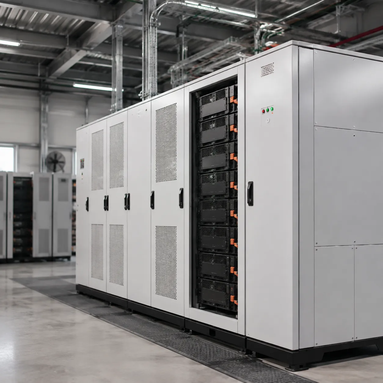
Selecting between a low-voltage (LV, typically 48V–100V DC) and a high-voltage (HV, 600V–1500V DC) architecture is a fundamental design decision for commercial and industrial projects. Operating a high voltage energy storage cabinet unlocks significant engineering advantages in conversion efficiency, installation footprint, and hardware savings over legacy LV designs.
| Engineering Parameter | Low-Voltage Systems (48V–100V) | High-Voltage Systems (600V–1500V) |
|---|---|---|
| Operating Current (at 100 kW) | 1,000 A – 2,083 A | 66.7 A – 166.7 A |
| Cable Gauge & Weight | Heavy-gauge copper / High weight | Standard-gauge cabling / Minimal weight |
| Round-Trip Efficiency (RTE) | ~82% – 86% | ~90% – 93%+ |
| Footprint per kWh | High (larger DC combiners & cables) | Compact, high-density modular racks |
| Expansion Limits | Limited (high current balancing issues) | Multi-cabinet, megawatt-scale expansion |
| Safety Mechanisms | Basic contactors, passive fuses | Multi-layer BMS, IMD, HVIL loops, auto-tripping |
System Efficiency and Energy Conversion Losses
Conductor heat dissipation follows Joule’s law ($P_{loss} = I^2R$). Because high-voltage systems deliver the same total power at a fraction of the current, resistive thermal losses across the DC bus, switches, and wiring are drastically reduced.
- Higher DC-to-AC Efficiency: A high-voltage DC bus couples directly with modern three-phase Power Conversion Systems (PCS) and grid-tied inverters without needing bulky step-up DC-DC converters.
- Minimized Thermal Stress: Lower current eliminates localized heating on cell terminals and busbars. Pairing our high-voltage architecture with an advanced liquid-cooled energy storage cabinet stabilizes cell temperatures within a strict ±2°C window, boosting system round-trip efficiency (RTE) above 90%.
Cable Sizing, Current Load, and Installation Complexity
Low-voltage setups handling high power require massive copper cross-sections, complex parallel bussing, and bulky terminal lugs.
- Reduced Copper Utilization: A high voltage battery rack system cuts current throughput by up to 90% compared to a 48V battery bank. This allows the use of flexible, smaller-diameter cables and smaller conduit sizes.
- Streamlined On-Site Installation: Contractors spend fewer labor hours pulling heavy wire. Lighter raceways, compact gland plates, and standardized quick-connect DC plugs speed up physical interconnection and reduce installation costs.
Scalability for Large Commercial Applications
Low-voltage architectures face severe scaling limits; paralleling multiple low-voltage strings causes circulating currents, unbalanced charging states, and prohibitive DC combiner costs.
Our high-voltage modular battery packs connect in series to reach the required DC bus voltage, and multiple high-voltage racks can then be safely combined in parallel. This clean electrical topology enables seamless scaling for commercial battery energy storage system deployments ranging from 100 kWh to several megawatt-hours, matching the architecture used in scalable battery energy storage systems for utilities.
Safety Protocols and Integration Requirements
While low-voltage systems operate below typical touch-safe electrical hazard limits (<60V DC), high-voltage equipment demands robust, automated safety engineering:
- Insulation Monitoring Devices (IMD): Continuous real-time detection of ground faults and DC isolation breakdown.
- High-Voltage Interlock Loops (HVIL): Hardware interlocks that instantly drop the main DC contactors if any connector or maintenance panel is compromised.
- Integrated Disconnects & Arc Protection: Fast-acting DC contactors, high-rupture-capacity (HRC) fuses, and manual service disconnects (MSD) ensure safe physical isolation during planned servicing.
Site Preparation and Installation Requirements
Proper site preparation ensures your high voltage energy storage cabinet operates safely, meets local building codes, and passes commissioning without delays. We design our systems for straightforward deployment, but high-voltage DC equipment requires strict adherence to civil, electrical, and environmental standards.
Site Deployment Workflow
1. Civil Works Concrete foundation ↓ 2. Enclosure Placement Clearance verification & anchoring ↓ 3. Cabling & Grounding DC/AC connections & protective earth (PE) grounding ↓ 4. Testing & Commissioning Site acceptance testing (SAT)
Civil Foundation and Floor Loading Requirements
A fully populated high voltage battery storage cabinet concentrates substantial mechanical mass over a compact footprint.
- Load-Bearing Capacity: Standard commercial units exert point loads ranging from 1,200 kg to over 3,500 kg. Concrete slabs must support at least 1,500–2,000 kg/m² depending on rack capacity.
- Foundation Quality: For ground-mount installations, pour a reinforced concrete pad (C25/C30 minimum) with a thickness of at least 150 mm to 200 mm, extending 300 mm beyond the cabinet edges.
- Leveling and Anchoring: The surface level tolerance must remain within ±2 mm per meter. Anchor the cabinet using seismic-rated M12 or M16 expansion bolts through the base frame mounting holes.
- Drainage and Ingress: Elevate outdoor pads 100 mm to 150 mm above maximum local flood lines, grading the perimeter away from the enclosure base.
Electrical Wiring, DC/AC Interconnection, and Grounding
High-voltage architectures operate at lower currents than low-voltage systems, enabling thinner conductor cross-sections, but they require uncompromising insulation and bonding protocols.
Electrical Termination Architecture
Battery Strings (Up to 1000 V+ DC) ↓ High-Voltage Control Box Fuse / Contactor / BMS ↓ High-Voltage DC Cabling Shielded, double-insulated cables ↓ Power Conversion System (PCS) / Hybrid Inverter ↓ AC Distribution Panel / Grid Interconnection
Equipotential Grounding Network Dedicated protective earth (PE) busbar → Grounding and bonding of equipment enclosures
- DC Interconnection: Route high-voltage DC runs through rigid, dedicated metal conduits separate from AC and low-voltage communication lines to prevent electromagnetic interference (EMI). Use 1,500V DC-rated, flame-retardant, double-insulated copper cables.
- AC Interconnection: Connect the paired Power Conversion System (PCS) to the facility switchboard through a dedicated lockable isolation breaker sized according to continuous rated output.
- Grounding and Bonding: Connect the cabinet's internal PE ground busbar directly to the site earthing grid. Earth resistance must measure below 4 ohms. Ensure all structural panels, rack trays, and cable gland plates maintain continuous equipotential bonding.
Indoor vs. Outdoor Enclosure Considerations
Selecting where to site your industrial energy storage cabinet depends on available square footage, local environmental factors, and building containment codes. For exposed external sites, deploying an outdoor battery energy storage system with LiFePO4 battery provides the necessary weatherproofing, thermal insulation, and integrated protection required for harsh operating climates.
| Requirement Parameter | Indoor Installation | Outdoor Installation |
|---|---|---|
| Minimum Enclosure Rating | IP20 to IP31 (NEMA 1 / 2) | IP54 to IP55 (NEMA 3R / 4) |
| HVAC & Thermal Management | Relies on facility HVAC or ducting | Dedicated closed-loop cabinet air conditioner or liquid chiller |
| Clearance Requirements | 1,000 mm front; 800 mm rear/sides for maintenance | 1,200 mm perimeter clearance; 3,000 mm from structures |
| Fire Code Compliance | NFPA 855 separation, indoor sprinkler/ventilation | Setback distances from property lines; gravel buffer zone |
| Sunlight & Climate Shielding | Not applicable | Add sunshades in high-UV, extreme ambient heat zones |
Commissioning and Pre-Operational Testing Procedures
Never energize a high voltage BESS cabinet without running through systematic pre-commissioning checks. We follow a strict site acceptance testing (SAT) process before closing the main DC contactors:
- Mechanical & Visual Audit: Check bolt torque on battery terminal busbars using a calibrated torque wrench. Verify cable seals, gland integrity, and ensure zero debris remains inside the enclosure.
- Insulation Resistance (Megger Test): Test DC positive-to-ground and negative-to-ground paths using a 1,000V or 2,500V insulation tester. Values must exceed 10 megohms before closure.
- High-Voltage Interlock Loop (HVIL) Verification: Verify that opening any service disconnect, emergency stop (E-stop), or rack access panel immediately triggers the HVIL circuit and trips the main breakers.
- BMS Telemetry and Communication Check: Power up the low-voltage auxiliary circuits. Confirm the BMS accurately reports cell voltages, module temperatures, total rack string voltage, and establishes Modbus/CAN links with the PCS.
- Controlled Power-On & Trial Cycling: Manually close pre-charge circuits to avoid inrush current damage. Run an initial charge and discharge cycle at a low C-rate (0.2C) while monitoring thermal imaging across every connection point.
Maintenance, Health Monitoring, and Service for High Voltage Energy Storage Cabinets
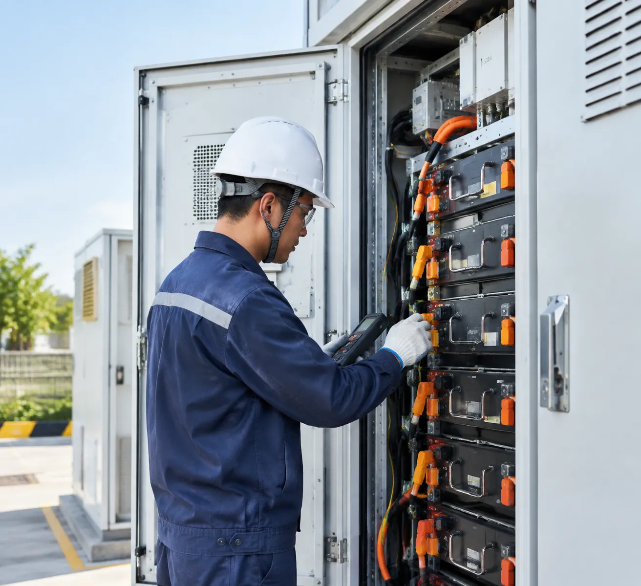
Routine Inspection and Preventive Maintenance Schedules
To ensure uninterrupted uptime and retain enclosure integrity, we recommend standard maintenance intervals structured around key mechanical, electrical, and thermal checks:
| Maintenance Interval | Component Focus | Key Service Tasks |
|---|---|---|
| Monthly (Visual & Automated) | Enclosure & Environment | Check external air intakes, HVAC exhaust filters, door seals, and clear any BMS alarm logs. |
| Semi-Annual (Mechanical & Thermal) | Thermal Management & Safety | Inspect HVAC/liquid cooling fluid levels, pressure gauges, aerosol fire suppression actuators, and test emergency stop circuits. |
| Annual (Full System Electrical) | Power Connections & Racks | Perform thermal imaging on DC busbars, re-torque high-voltage terminals to spec, test insulation resistance, and verify ground continuity. |
Our modular rack architecture allows technicians to isolate and service individual battery packs or cooling modules without taking the entire high voltage BESS cabinet line offline.
BMS Telemetry, State of Charge (SOC), and State of Health (SOH) Tracking
Our multi-tier Battery Management System (BMS) continuously records critical operating parameters at the cell, pack, and rack levels. This data streams directly to localized interfaces and supervisory cloud platforms:
- Cell-Level Precision Tracking: Continuous monitoring of individual cell voltages, pack delta-temperatures, and internal resistance to prevent localized cell degradation.
- Dynamic Active Balancing: Automatic equalization of charge across all series-connected cells during float cycles to preserve usable capacity.
- Predictive SOH Algorithms: Real-time computation of remaining capacity, cycle life count, and internal impedance growth over time.
Integrating your system with a dedicated factory energy management solution for real-time monitoring allows facility managers to cross-reference battery telemetry with facility load profiles, spotting thermal anomalies and capacity loss before they cause unplanned outages.
Firmware Updates and Remote Diagnostic Support
Every commercial battery energy storage system we deploy includes end-to-end connectivity for off-site diagnostics and lifecycle software management:
- Over-the-Air (OTA) Updates: Secure remote deployment of BMS logic patches, battery charge curve optimizations, and inverter communication protocol updates.
- Automated Fault Isolation: When anomalous voltage drops or thermal warnings occur, the system flags the exact module, logs high-resolution pre-fault waveform data, and isolates the string via the high-voltage contactors.
- Remote Engineering Diagnostics: Our technical service team can access historical trend logs, evaluate string degradation curves, and assist on-site contractors with guided troubleshooting without requiring immediate dispatch for minor software calibration.
Customization and Sizing Guide for High Voltage Energy Storage Cabinets
Selecting the right high voltage energy storage cabinet requires a precise engineering approach. We tailor each system to match your site's specific load profiles, operational goals, and physical site constraints, ensuring maximum return on investment and long-term reliability.
Calculating Required Battery Capacity and Discharge Power
To size a commercial battery energy storage system correctly, we evaluate two primary metrics: continuous power rating (kW) and usable energy capacity (kWh).
- Power Rating (kW): Determined by the peak load you need to shave or the critical loads required during backup operation.
- Energy Capacity (kWh): Calculated by multiplying the required discharge power by the desired backup or peak-shaving duration (hours), accounting for depth of discharge (DoD, typically 90%) and system round-trip efficiency (RTE).
$Required Capacity (kWh) = frac{Load (kW) × Runtime (h)}{DoD × System Efficiency}$
| Application Target | Typical C-Rate | Discharge Duration | Sizing Priority |
|---|---|---|---|
| Demand Charge Management | 0.5C to 1C | 1 to 2 hours | High peak discharge power |
| Solar Self-Consumption | 0.25C to 0.5C | 2 to 4 hours | Usable energy capacity (kWh) |
| Microgrid & Off-Grid Backup | 0.5C | 4 to 8 hours | Continuous power & surge tolerance |
Selecting Compatible PCS, EMS, and Solar Inverters
A high voltage ESS cabinet requires seamless communication with power conversion systems (PCS) and energy management systems (EMS). We ensure complete hardware and software compatibility across all system components:
- DC Voltage Window Matching: We align the DC bus voltage of our high voltage lithium battery cabinet (typically 500V–1000V DC) with the operating MPPT and DC input ranges of your PCS or hybrid inverter.
- Communication Protocols: Native integration via CAN 2.0B, RS485, and Modbus TCP/IP allows zero-latency telemetry exchange between the BMS, inverter, and central EMS.
- System Topologies: We support both AC-coupled retrofits when adding battery storage to solar systems and DC-coupled architectures for new, high-efficiency solar-plus-storage projects.
Custom Enclosures, Thermal Management, and Fire Suppression
Operating environments vary dramatically. We configure the mechanical and environmental protection of each outdoor battery energy storage system to match regional climate requirements:
- Enclosure Protection: Choose between IP54 standard enclosures for sheltered industrial locations and IP55 / NEMA 3R/4X rated outdoor cabinets with C5-M anti-corrosion coatings for coastal or harsh industrial environments.
- Thermal Management: We supply forced-air HVAC systems for moderate climates and advanced liquid cooling ESS cabinet designs for high-ambient-temperature regions or heavy continuous cycling (1C rates), maintaining cell temperature uniformity within le 3 °C.
- Fire Safety Integration: Options include multi-stage aerosol systems, clean agent gas suppression (FK-5-1-12 / Novec 1230), and integrated water-mist piping with automated thermal runaway and deflagration venting.
OEM Branding, Layout Configurations, and Modular Expansion
For system integrators, EPCs, and project developers, we provide complete flexibility in design and deployment for turnkey battery storage for solar PV system factory solutions:
- Modular Rack Expansion: Scalable high voltage battery rack system architectures allow you to connect multiple cabinets in parallel on a single DC or AC bus to scale from 100 kWh to multi-megawatt-hour projects.
- Custom Cabinet Layouts: Configurable top or bottom cable entry, separate power and control compartments, and flexible footprint layouts to fit tight indoor electrical rooms or containerized outdoor pads.
- OEM & Private Label Services: Custom industrial exterior colors, silkscreened logos, tailored human-machine interface (HMI) software branding, and specialized packaging for global shipping.
Frequently Asked Questions (FAQ)
What is a high voltage energy storage cabinet?
A high voltage energy storage cabinet is an integrated enclosure housing series-connected lithium battery modules that operate at elevated DC voltages—typically between 200V and 1000V+ DC. Designed for commercial, industrial, and microgrid applications, these systems connect directly to central or string Power Conversion Systems (PCS), minimizing transmission losses and maximizing conversion efficiency. Explore our standardized energy storage cabinets to evaluate engineered configurations for industrial installations.
What voltage range does a high voltage battery cabinet support?
Standard high-voltage battery cabinets support nominal DC voltages ranging from 200V DC up to 1000V DC, with utility-scale designs reaching 1500V DC. For most commercial and industrial (C&I) applications, a rack operates between 500V and 800V nominal DC, aligning directly with common 400V/480V 3-phase grid-tied inverters without requiring heavy step-up transformers.
Can the high voltage cabinet integrate directly with solar PV arrays?
Yes. High-voltage cabinets integrate via two primary topologies:
DC-Coupled: Connected directly to high-voltage hybrid solar inverters, allowing solar DC power to charge batteries without converting back and forth to AC, yielding higher round-trip efficiency (RTE).
AC-Coupled: Connected alongside existing solar PV systems via a dedicated bidirectional PCS on the AC distribution bus, making it ideal for retrofitting existing facilities.
Can the storage cabinet operate in off-grid or microgrid mode?
Yes. When paired with a grid-forming PCS and local Energy Management System (EMS), the cabinet provides black-start capability and switches from grid-following to grid-forming mode in under 20 milliseconds. Our parallel battery energy storage systems provide continuous power to islanded facilities, diesel-hybrid microgrids, and critical commercial loads during grid failure.
Is the cabinet suitable for outdoor installations?
Yes. Outdoor units are built inside IP54 or IP55/NEMA 3R weather-rated enclosures. They feature:
Multi-stage C3 to C5 anti-corrosion powder coatings.
Industrial-grade liquid cooling or smart HVAC air conditioning.
Dust, moisture, and extreme ambient temperature protection (-20°C to +55°C).
What battery chemistry is used in high voltage BESS cabinets?
We use premium Lithium Iron Phosphate (LiFePO4 / LFP) cell chemistry. LFP is the global standard for industrial energy storage due to its exceptional thermal stability, non-combustible chemical profile, non-toxic composition, and superior lifespan under continuous cycling compared to NMC chemistries.
How does the BMS prevent thermal runaway in high-voltage racks?
Our systems use a three-tier Battery Management System (BMS) architecture providing real-time protection:
Cell Level: Monitors individual voltage, impedance, and terminal temperatures.
Module/Rack Level: Automatically detects anomalies, balances charge states, and isolates electrical faults via high-speed DC contactors and pyro-fuses.
System Level: Triggers early warning protocols (detecting CO, H2, and smoke emissions) and engages localized aerosol or Novec 1230 fire suppression before thermal events propagate.
Can multiple energy storage cabinets be connected in parallel?
Yes. High voltage BESS cabinets scale linearly:
DC Paralleling: Multiple racks connect to a common DC bus via dedicated DC combiner cabinets.
AC Paralleling: Independent cabinet-PCS blocks synchronize across the facility's low- or medium-voltage AC switchgear, allowing capacity scaling from 100 kWh to tens of megawatt-hours (MWh).
What is the expected cycle life and operating lifespan?
At 0.5C/0.5C charge-discharge rates and standard ambient temperatures (25°C), our LiFePO4 high-voltage systems achieve 6,000 to 8,000+ full cycles at 80%–90% Depth of Discharge (DoD) before reaching 70% End-of-Life (EoL) capacity. Under normal commercial cycling patterns (1–2 cycles daily), this translates to a 10 to 15+ year operational lifespan.
How do I select the right cabinet capacity for commercial peak shaving?
To size your cabinet correctly:
1. Analyze 15-minute interval demand data: Review 12 months of utility bills to find recurring monthly peak kW spikes.
2. Define target demand limits: Determine the maximum kW reduction required to lower demand tariff brackets.
3. Calculate discharge duration (kWh): Multiply the required power reduction (kW) by the duration of the peak window (hours), factoring in system round-trip efficiency (typically 88–92%) and safe depth of discharge limits.